ABSTRACT
In this project, we investigate the performance of Raptor codes as candidates for channel coding for the wireless communication between access nodes. Very high data-rates are used, and processing uses more resources than transmission. Therefore, we need fast encoding and decoding algorithms for the channel coding. Raptor codes have linear encoding and decoding times, and can have very small overhead if they are properly designed. Hence, they are possible candidates.
We have implemented an encoding and decoding algorithm for Raptor codes, as well as an environment for simulation. The system requirements are expressed in terms of delay between the beginning of a transmission and the successful decoding, and storage required during the transmission and processing.
We have evaluated the performance of Raptor codes in terms of delay and storage as a function of system design parameters, in particular the number of nodes in the network, and the size of the packets. We show that if the size of the packets is properly chosen, Raptor codes can be useful for the application,and we explain the method for choosing the size of the packets. We also provide a way to calculate the delay and the storage for a given system configuration, in order for example to determinate the larger number of nodes or the larger of users such that the delay and the storage are acceptable.
RAPTOR CODES
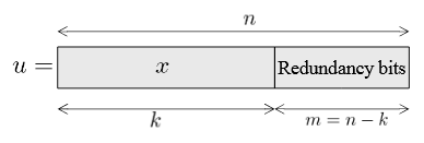
Figure 2.4. Code word obtained from a systematic encoder
A systematic encoder is such that the source information is directly present in the code word. For example, the first k bits of the code word are equal to the k message bits, and the remaining code bits are redundancy bits, as represented in Figure 2.4. The redundancy bits allow the decoder to detect and possibly correct errors in the received data. Once the code word is error free, the original message can be directly recovered.
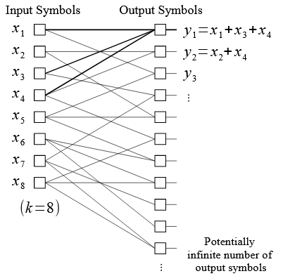
Figure 2.6. Bipartite graph for LT encoding, for k = 8
The relation between the input and the output symbols can be represented as a bipartite graph, as the one in Figure 2.6. The left-nodes represent the input symbols, and the right-nodes the output symbols. The edges of the graph link each of the output nodes together with the input nodes it is the sum of, called its input neighbors.

Figure 2.9. Operations at the intermediate nodes when they perform the Raptor decoding and re-encoding
Intermediate nodes can perform different operations. One possibility is for each intermediate node to decode the message and re-encode it before transmitting to the next node, as presented in Figure 2.9.
PERFORMANCE
The system requirements can be expressed in terms of delay per information bit and storage per information bit. In this chapter, we perform a delay and storage analysis based on the Raptor encoding and decoding algorithms that we have implemented in Matlab, in order to express the delay and the storage as a function of the number of output symbols.
- Complexity of the Algorithms
- Delay
- Storage
IMPLEMENTATION
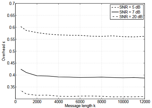
Figure 4.1. Overhead as a function of the message length k, for several SNR values
The first parameter we are studying is the message length k of the code, i.e., the number of input symbols. We performed simulations for different k, and the results in terms of overhead are presented in Figure 4.1. We can see that the overhead is approximately constant for k > 2 kbits. LT and LDPC codes have bad properties for smaller message lengths, and we do not consider small message lengths. In the following, we consider that k > 2 kbits, and that the overhead does not depend on k.
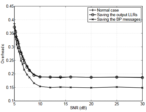
Figure 4.8. Overhead as a function of the SNR, for different methods
We have performed simulations with these two methods, and compared the results to the normal case. The corresponding overhead as a function of the SNR is presented in Figure 4.8. We can see that the overhead when saving the BP messages is lower than when not saving them. What actually happens is that the BP decoding algorithm converges faster when saving the messages, and a smaller number of iterations is needed for reaching the same performance in terms of overhead.
RESULTS

Figure 5.8. Multinode network
We consider the network presented in Figure 5.8, with a source node S, a destination node D, and a set of n intermediate nodes between them. As was studied in Section 2.10, the Raptor decoding can take place either at each intermediate node, or only at the destination node. In this section, we these two possibilities.
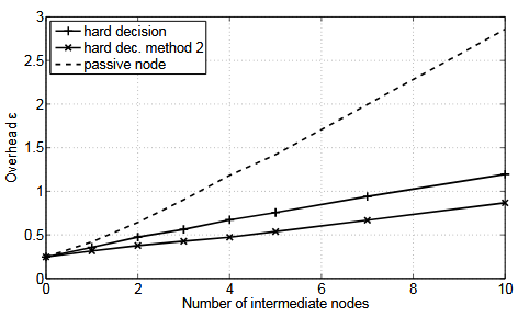
Figure 5.10. Overhead as a function of the number of intermediate nodes for SNR = 8 dB on each link
Figure 5.10 presents the results for higher SNR, 8 dB on each links. The overhead is still increasing with the SNR, though much less than in the previous case. Here the hard decisions perform better than the passive nodes. The error probability when taking hard decisions is low enough to prevent their propagation through the whole channel. On the contrary, with the passive nodes, the noise is added, and the errors propagate along the links.
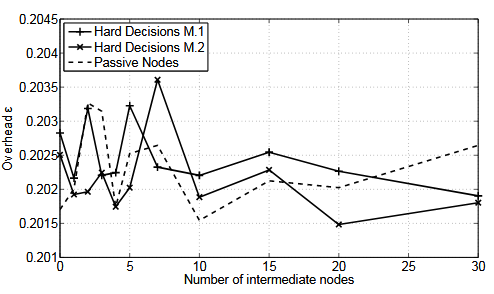
Figure 5.11. Overhead as a function of the number of intermediate nodes for SNR = 30 dB on each link
From Figure 5.11, at high SNRs, here 30 dB, the three methods have comparable performance, and the overhead only varies randomly within a small interval when increasing the number of intermediate nodes. The quality of the channel is so high that it is possible to increase the number of nodes without any loss in performance.
CONCLUSION AND FUTURE WORK
Conclusion
In this project, we have first implemented an algorithm for the encoding and the decoding of Raptor codes. We have also determined formulas to calculate the delay and the space consumption for a transmission, given the system configuration and the hardware implementation. These expressions were useful for choosing parameters for the algorithms, i.e., the precode, the LT degree-distribution, and the number of iterations of the BP algorithms.
They were also useful for performance analysis of the implementation as a function of system design parameters, in particular the size of the packets, the number of nodes and users, and the type of operations performed at the intermediate nodes. Finally, they allow to determinate the worst case, in terms of number of nodes for example, such that the delay and the space consumption are acceptable. We have also implemented a systematic version of Raptor codes, which allows for reducing the decoding time at high SNRs, but has non-linear encoding and decoding time.
Future Work
This thesis was an investigation on how Raptor codes would perform on SDNs. The goal here was not to optimize Raptor codes, and the system on which they would be implemented, as well as the exact requirements, were not fully defined yet. When they are, more optimization can be done on Raptor codes, in order to reach better performance. For example, the LT-degree distribution and the size of the packets can be better optimized.
Source: KTH
Author: Émilie Baudin
>> Simple Matlab Projects Base Papers for Engineering Students
>> Simulink Projects using Matlab for Engineering Students
>> Huge List of Matlab Projects with Free Source Code
>> More Matlab Projects based on Wireless Communication for Engineering Students