ABSTRACT
A realtime monocular (single camera) visual Simultaneous Localization And Mapping (SLAM) robot is built utilizing a server-node based computational approach. The core of the robot is a Raspberry Pi 2 with a Robot Operating System (ROS) wrapper over the Raspbian Wheezy Linux kernel. Different nodes from the robot communicate with the server to map its location based on its surroundings using ORB-SLAM, with loop detection and re-localization capabilities.
DESIGN PROBLEM
A rigid body in a 3-dimensional space generally has six degrees of freedom – namely three rotational ( commonly called pitch, roll & yaw ) and three translational ( commonly refered by x, y & z axes). This combination of the position and orientation of the body is commonly referred to as the pose.
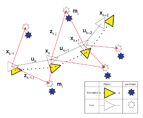
Figure 2.1: A Robot in an unknown environment.
Consider a robot moving in an unknown environment as depicted in Fig. 2.1 with
xk : The state vector describing the location and orientation of the vehicle.
uk : The control vector, applied at time k – 1 to drive the vehicle to a state xk at time k.
mi : The vector describing the location of the ith landmark which is time invariant.
zik : An observation taken from the robot of the location of the ith landmark at time
RELATED WORK
Today, when one looks at the developments that have occured in different fields, Computer Vision is one among the disciplines where a lot of devel- opment has occured. Several advanced algorithms have been developed to extract meaningful data from image data. The field of using visual data to perform SLAM is called Visual SLAM.
The objective of Visual SLAM algorithms is to estimate the pose of the cam- era which is moving and map the geometric structure and appearance of the environment the camera is moving in. The most vital problem in Visual SLAM is obtaining correspondence throughout the image stream. This results in them having a bad response when there are abrupt changes in the motion of the camera. Modern Visual SLAM algorithms obtain this correspondence throughout the images captured using Sparse feature matching techniques and construct maps using a composition of simple geometric constructs like points. The resulting map provides a sparsely furnished, incomplete representation of the environs
- Feature Descriptors and Detectors
- ORBSLAM
IMPLEMENTATION
Broadly, the architecture can be divided into the robot (Raspberry Pi 2 based) and server (Laptop) communicating via the internet. The robot, also known as the slave in the system, is built using Raspberry Pi 2 along with key components (nodes) such as parallax continuous rotation servos, the Inertial Measurement Unit (IMU) MPU 9250 and the Raspberry Pi camera module.
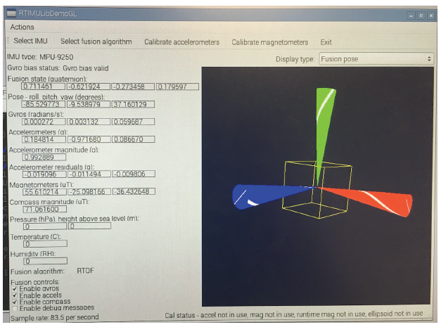
Figure 4.2: IMU initial test.
Camera Module was module on top and the IMU was placed at the center tip of the robot. Both are placed as accurately parallel to the ground.
DESIGN VERIFICATION
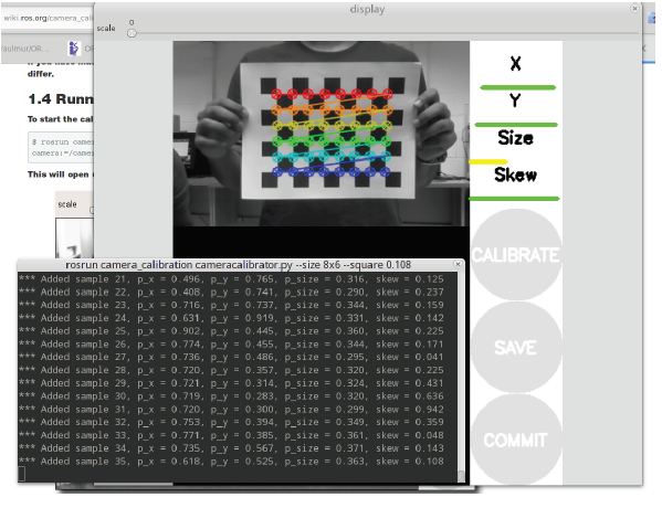
Figure 5.1: Pi Camera Calibration.
The calibration of the Raspberry Pi camera module is done using OpenCV as show in fig. 5.1. This is performed using Monocular calibration by cal- ibrating the camera against a 8×6 checkerboard of 108mm squares. The calibration file generated is then modified to suit needs for ORB-SLAM 2 implementation.
Experimental Trials
Fig. 5.2 depicts the initial run of ORB-SLAM. The system examines for sufficient features for tracking in the environment in order to initialize. When the necessary threshold of features detected is achieved, it completes the initialization.
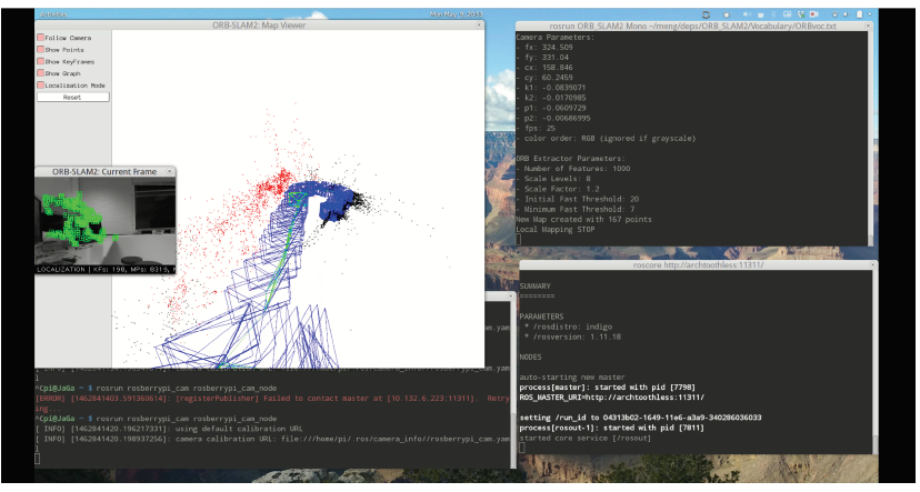
Figure 5.6: Trial 4 : Results.
Until Trial 4, the mode of operation of ORB-SLAM 2 was SLAM mode which was used in mapping the environment surrounding. Shown in Fig. 5.6 is on operation of Localization Mode where based off the surroundings already mapped, it recognizes its location.
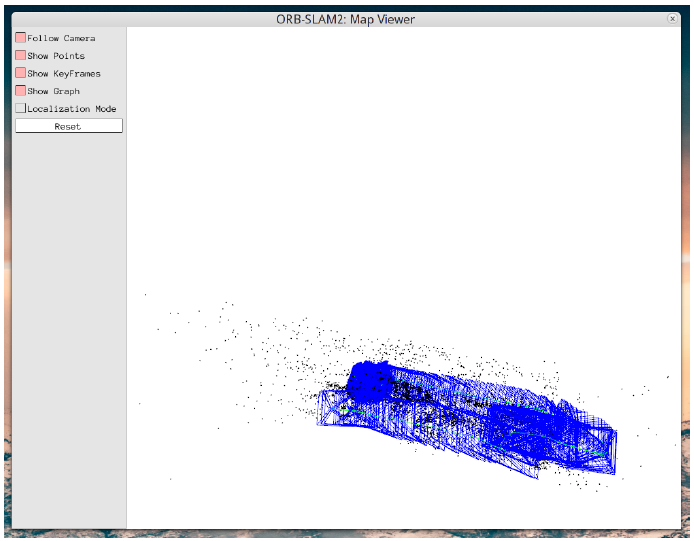
Figure 5.7: Trial 5 : Loop Closure.
The loop closure feature of the SLAM implementation was verified and is shown in Fig. 5.7.
CONCLUSION
The system was successfully built. It worked to our expectations. The system transmitted monocular images at frame rate of 25 fps at 320×200 resolution and the trajectory was tracked in the server successfully.
The performance was as expected in scenarios where the environment had a lot of different types of object or textures. In scenarios with very similar or same texture, the system was not able to detect ORBs and failed to initialize. This was an expected result. As real world generally has a lot of objects and varied texture, this should not prove to be a problem.
Source: Cornell University
Authors: Gautham Ponnu | Jacob George

