
ABSTRACT
Motivated by high energy costs, people and organizations want to cut back on their energy consumption. However, the only feedback consumers typically receive is a monthly bill listing their total electricity usage (in kWh). Some companies have begun developing systems that allow households and organizations to monitor their energy usage for individual circuits.
Available systems are expensive so a CU engineering senior design team has designed, fabricated, and tested a system for use at Cedarville University. The AC power monitoring system has the ability to measure energy consumption for each individual circuit in the breaker panel, store the data, and then provide the user with visual feedback on energy usage behavior. The basic system provides the proof of concept for future senior design teams.
After more testing is completed, further development of this product will be needed by other senior design teams. Eventually, this energy monitoring system could be expanded to include larger loads such as HVAC systems and refrigeration units. It is also envisioned that future projects might be able to provide the user with suggestions for changing and improving energy usage behavior. Failure prediction of equipment on individual circuits could also stem from this initial project. For this project, it has been clearly shown that the concept is feasible, expandable, and cost-effective.
ENGINEERING DESIGN
To meet our objectives and specifications , we have developed the following design for our project. Figure 1 depicts the analog portion of our system, while Figure 2 depicts the digital portion.

Figure 1: Analog Design

Figure 2: Digital Design
RASPBERRY PI
The Raspberry Pi is the piece of the design that takes our raw digital data, turns it into something meaningful, and send s it off out of our system’s local environment and into the cloud. We needed a device that could communicate with a low level microcontroller as well as send this data over the internet. The Pi provided a perfect solution to this problem as it has nice GPIO pins as well as Ethernet and Wi-Fi capabilities. The Pi is responsible for two things, data acquisition and calculation and sending the data to the cloud. This is discussed in the following two sections.
FINANCES
After completing our senior design project, we found that we finished at a reasonable expense. Table 1 in the appendix shows every expense from this year. We finished under our original budget by $362.37. The appendix also contains Table 2, which shows the per unit breakdown cost of our system. It comes out to be $368.55. Table 1 below summarizes the developmental cost of this product.
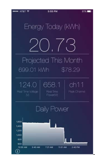
Figure 4 : Dashboard
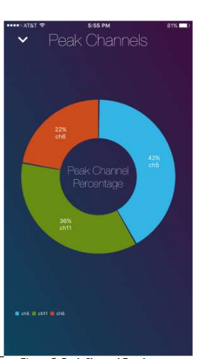
Figure 5: Peak Channel Breakout
RECOMMENDATIONS FOR FUTURE STUDENTS
We proved that a system like this can work, and we have laid the groundwork for this project to be continued. If a team were to take this project next year, we would have some recommendations for them. Hopefully we can provide an easy transition for them to expand the system where we have left off. Our recommendations are as follows:
- Replace the operation amplifiers that are currently being used. We chose the LF353 because that is what we have in the lab, but they are an old technology and not very efficient. They draw up to 4 mA each, which burdens the power system. You should use m or e efficient two-channel operation amplifiers.
- Change the capacitor sizes that go with the linear regulators to eliminate all ripple in the voltage. We simply soldered on bigger through – hole capacitors because the footprint of the PCB did not allow for surface mount components to be changed.
- Add another analog to the digital conversion channel to read in the DC voltage offset to the PIC. We did not have this, so once we measured the DC offset voltage and put the system in the box we were stuck with it. If you run this voltage into the PIC then you would have a very accurate value when doing calculations.
- Fix channel 7’s input into the PIC. The input pin on the PIC for channel 7 is already being used by the PIC for something else. You would simply have to change the trace on the PCB design.
- Expand the system to monitor both bus bars in the circuit breaker panel. We have only done one side due to cost reasonability, but we would only have to make a duplicate PCB. Monitoring both voltages would provide very accurate results in calculations. In order to monitor both sides of the breaker panel, we are making an assumption with the voltage waveform and shifting it either 120 or 180 degrees, depending on the type of building. This is a fair assumption, but monitoring both voltages would be more accurate.
- Figure out a good way to monitor 240 V breakers. This was out of the scope of our project, but we foresee this being an interesting issue to solve.
- The current transformers we chose, the SCT – 130 – xxx series, goes up to 100 A, which is hopefully enough for all future endeavors. But be aware that if you use the 100 A version you will need to add a burden resistor to its output.
- We were sequencing through channels because the PIC did not have enough physical storage to do every channel at once. If you wanted to collect all data at all times, you could possibly use a PIC with more internal storage.
- Build a more permanent backend. We used Google Firebase so we could focus on more pertinent parts of the project, but developing your own backend might be better.
- Look to expand the feedback portion of the cellular application to provide energy behavior suggestions and cost saving tips.
- Expand the mobile application to operate on an Android device.
Source: Cedarville University
Authors: Jared L. Newman | Luke M. Tomlinson | Grayson H. Dearing | Frederick G. Harmon
>> Huge List of Matlab Projects with Free Source Code
>> Simple Matlab Projects Base Papers for Engineering Students
>> Best Matlab Project Ideas for Engineering Students with Full Project Materials
>> 200+ Matlab Projects based on Control System for Final Year Students