ABSTRACT
Most subwoofer systems have difficulties producing frequencies in the low end of the hearing spectrum due to the added power requirements and instabilities. Active controls can transform the audio signal without changing physical characteristics and ultimately generating a more impressive audio system. A Linkwitz transform crossover was implemented to extend the low end frequency response of a sealed enclosure. A graphical user interface in MATLAB was written to aid in selection of components, driver and enclosure volume.
The circuit board was built and integrated with a home theater system inside of a couch and tested with a Real Time Analyzer. The Linkwitz crossover was shown to extend the frequency response, transient response and improve the subwoofer system while reducing the required enclosure volume.
ANALYSIS
The loudspeaker parameters can be attained from the manufacture and the desired Fs and Q value of the transformed system are achieved by calculating the proper resistor and capacitor values in the Linkwitz transform circuit. The subwoofer and sealed enclosure frequency response must be understood prior to transforming the Fs and Q values. The loudspeaker free air resonance Fs, total compliance Qts and desired enclosure volume must be known.
THEORETICAL RESULTS

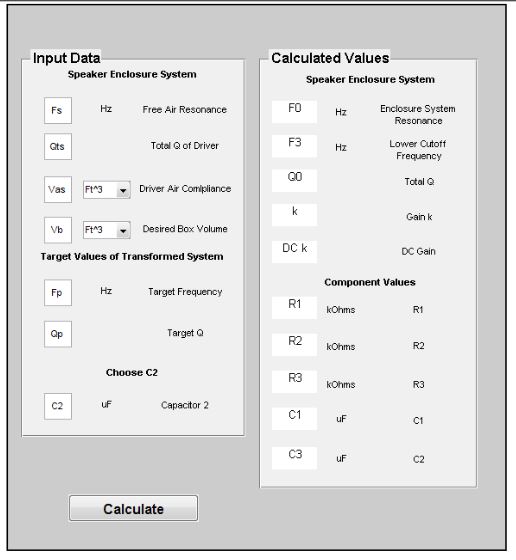
Figure 5. Input and Calculated Values of GUI
The purpose of the GUI is to aid in component calculations in order to optimize desired frequency response. The user must input the loudspeaker Vas, Fs, sealed enclosure volume and C2 value which generates the frequency response, phase response and component values. By analyzing various possibilities a more desirable system can be built for a more enjoyable listening experience. The layout of the GUI is shown Fig. 5 without the graphs.

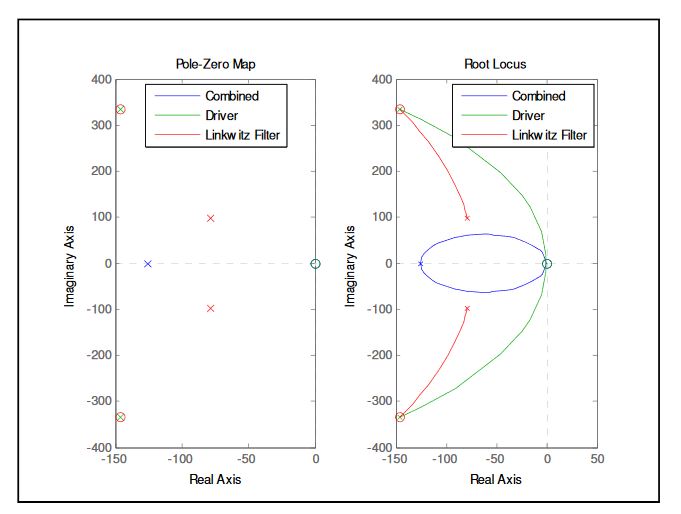
Figure 7.a. Pole Zero Plot b. Root Locus Plot
The pole-zero and root locus plots are shown in Fig. 7, which shows how the Linkwitz transform crossover alters the input to the desired output serving as an open loop signal controller. The driver and enclosure system is composed of two complex poles and a set of real zeros. The Linkwitz filter takes the input of the driver system and cancels the driver complex poles by placing two complex zeros on top which is apparent in Fig. 7. A set of poles are placed closer to the real axis to achieve the desired combined system with real zeros at the origin and real poles.
BUILDING CROSSOVER AND SYSTEM INTEGRATION

Figure 9. Linkwitz Transform Crossover with Phase Inverter
Once the system reaches a satisfactory response the Linkwitz transform crossover can be built for integration and test with an audio system. The final circuit used is composed of the Linkwitz transform circuit along with a signal phase inverter to gain greater control during the audio tuning process. The circuit is shown in Fig. 9 below.

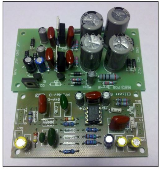
Figure 11. Completed Linkwitz Crossover and Power Supply
A goal of 5 % discrepancy was the requirement for resistor and capacitor selection which was achieved by combining resistors in series and capacitor in parallel noted by a + sign in the “value used” column. By combining components the 5% tolerance requirement was easily achieved. The other components used are listed in the appendix corresponding with circuit number in the diagram. The components were measured and soldered to the printed circuit boards and the final completed board s are shown in Fig. 11 below. The top board is the power supply and the bottom is the Linkwitz transform circuit used for the final integration.
TESTING AND APPARATUS
After system functionality was attained, testing is required to verify the performance of the transformed system. Two methods of testing were considered which were a real time analyzer and the human ear. A Real Time Analyzer (RTA) can gather empirical data for comparison but human ears will ultimately decide if the new system has really improved or not. However, the RTA can measure and dictate exactly where the improvements have been made along the frequency response while the human ear can only aid in decided if the entire system is better or not.
RESULTS AND DISCUSSION

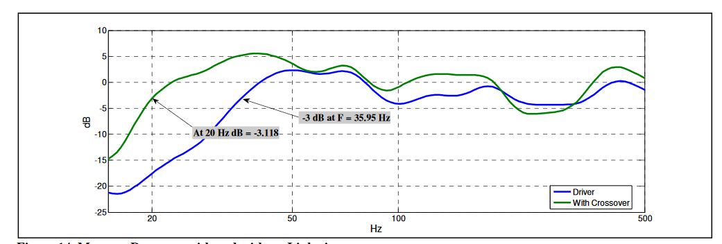
Figure 14. Measure Response with and without Linkwitz crossover
Figure 14 shows the actual achieved F3 just above 20 Hz which is very close to the 20Hz goal. The cutoff frequency before the addition of the crossover was measured to be 35.95 Hz. The data reveals the cross over performance producing tremendous results easily heard at low frequencies. The optimum frequency response of an audio system would be as flat as possible along the 0 dB axis. The system response shows dips and humps but both are consistent implying other parameters are affecting the response.
CONCLUSION
The Linkwitz transform crossover was shown to be a great addition to an existing home theater system. The ability to transform the complex poles to real axis poles is the foundation of the circuitry yielding a fairly simple but effective and inexpensive circuit. Other passive systems tend to require a larger enclosure volume and transient response is sacrificed for sound pressure level and lower frequency reproduction. The Linkwitz crossover sacrifices slight sound pressure level but the results are well worth the tradeoff especially when space is an issue.
The GUI designed aided in the component value, driver and enclosure selection to build a prototype from a theoretical system. The crossover performed to a very satisfactory level and integration of the system inside a couch generated great results that any audiophile can appreciate. For future consideration the addition of an equalizer would minimize variations from the 0 dB axis in order to optimize and build a dream home theater system for audio enjoyment.
Source: California Polytechnic State University
Author: Luis Dominguez
>> 200+ Matlab Projects for Control System for Final Year Students
>> 80+ Matlab Projects based on Power Electronics for Engineering Students
>> More Matlab DSP Project Ideas for Final Year Students