EXECUTIVE SUMMARY
Our designated stakeholder has identified that he wishes for the design team to conceptualize a system for wheelchair uses that reduces fatigue and decreases the chance for chronic musculoskeletal issues. Some of the alternatives designs that were considered included a lever-arm type extension to allow more efficient power delivery for the user to the hand rim with the added benefit of ergonomic improvement and the incorporation of a speed control algorithm that increased speed command with respect to a greater torque input form the wheelchair user.
The design that we chose to implement is advantageous because a pre-determined torque threshold may be set and adjusted to prevent the wheelchair user from sustaining injury from overstraining muscles and because the torque threshold prevents the motor from being continuously activated. This not only saves battery power but also ensures that wheelchair users do not experience muscle degradation from lack of use.
The designed electromechanical system consists of an electromagnetic hub motor, a driver that supplies power to the motor, an Arduino microcontroller unit, a breadboard for electronic connections, and 5 strain gauges. The proposed system will have the features of signal communication from strain gauges to an Arduino MCU, where the signal is to be processed and sent to the motor driver upon the strain signal exceeding a certain threshold.
The motor driver will provide the hub motor with electrical power, which will activate it and allow it to provide mechanical work to assist the wheelchair user with propulsion. The ability of the system to meet manufacturing specifications will be confirmed by simulation in Solidworks and Simulink. The results of the coordinated system featured realtime strain measurement from the gauges situated on the aluminum faceplate. The next step in the process is the coordinate the serial data from the receiver to the Arduino MCU and making physical connections between the MCU and the hub motor.
BACKGROUND
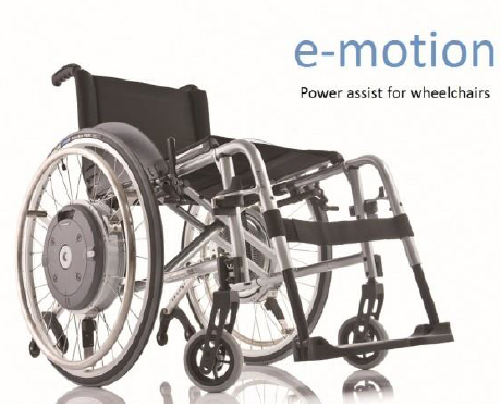
Figure 1: Alber e-motion power assist wheelchair.
The Alber e-motion power assist wheelchair delivers power to the wheelchair to assist users in all propulsion scenarios so the user gets the fatigue reducing benefits of the wheelchair but the motor is consuming more battery power so it is constantly being engaged. Alber emotion reviews have stated complaints of a snapping hand rim and user tipping backwards/forwards.
PROBLEM DEFINITION
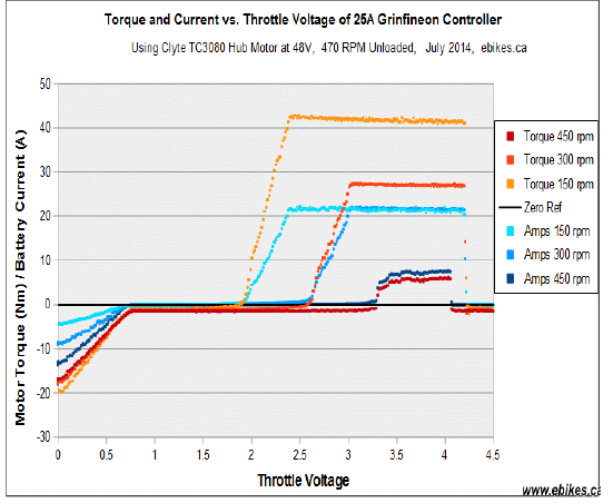
Figure 3: Relationship between driver throttle voltage and motor torque/battery current.
The Arduino MCU will provide a throttle voltage via pulse-width modulation and the magnitude of the voltage signal will be determined by the duty cycle of the pulse-width modulated signal. The pulse-width modulated signal is the passed through a RC low-pass filter to convert it to an analog signal and passed to the motor driver.
CONCEPT DEVELOPMENT

Figure 4: Lever Propulsion Wheelchair.
Our initial design would essentially follow the design for a traditional push-rim activated wheelchair, but would contain an adjustable lever along with a motor to create mechanical advantage for the patient. One goal of the wheelchair is to increase patient comfort using ergonomic principles.
PRODUCT DESCRIPTION
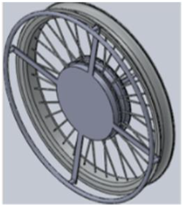
Figure 6:Design of Our System.
As has been mentioned many times previously, the design has four primary components. These are the wheel, the motor, the hand-rim device, and the control system. For the purposes of this semester our team only developed the hand-rim device. The wheel and motor are available for purchase online and should be capable of connecting to the final product with relative ease.
The way the rosettes were mounted and wired allowed for the collection of average strain data across the whole part. This was beneficial for our use because it ensured that there was not one “hot spot” that would provide more assistance that any other location. A picture of the mounted rosettes can be seen in the figure.
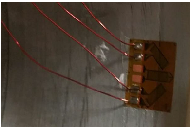
Figure 8: Mounted Strain Gauge.
The last component was the wireless transmitter. This was necessary because a motor has a stationary and rotating component. In order for our device to function, one of the components would have to transmit data without being in physical contact with the other components. The method we chose to accomplish this was a wireless transmitter. The transmitter and the node that receives the data can be seen in the figure below.
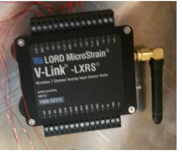
Figure 9: Wireless Node by LORD MicroStrain.
DESIGN EVALUATION
There was only one test conducted thus far on the wheelchair fatigue reducing prototype. This test was to evaluate the use of strain gauges, placement inside the aluminum hub, and the overall design of the outer hub to attach to an already acquired motor. First to cover the use of strain gauges. Through the research they were shown to be the best device to measure the strains associated with the hub when a torque is applied to the hand rim.
Solid works simulation with a 10-pound load showed that there were strains throughout the hub. This became the location for the strain gauges and were determined to be placed in a 4 node Wheatstone bridge arrangement around the inner face of the hub. The strain gauges were wired in to a wireless transmitter to avoid tangling wires when rotating in a real world scenario.
RECOMMENDATIONS AND FUTURE WORK
The above section mentions all of the features that prove this option can perform very well when compared to the other designs. The whole system can be bolted on to an existing motor with a few modifications to the motor casing. This also allows the hub to be easily accessed to work on the transmitter, strain gauges, and wiring should anything arise. The hand rim will be removed from its normal position on the wheel to be attached to the arms on the hub using the same hardware. Portions of the arm nearest to the hand rim need to be filled down and optimized to be sure the user does not injure themselves.
Recommendations and future work would be first to start testing with different techniques and designs of the hub assembly including dimensions and materials. This testing will further investigate the best design to optimize strains without sacrificing structural integrity or longevity of the system. Next would be to find the proper placing of the strain gauges to ensure that the only measurement being detected is the torque and not the effect of the arm’s movement parallel to the axis of the wheel axle.
The next steps in the process after finding the best combination of factors to get the best results out of the strain gauges and the transmitter. Signals in the software can then be used through several tests for known forces and known torques to get a range of values that can be used to send signals to the controller to tell the motor to turn on and what the power output should be based on how strong of a torque is being applied to the rim.
Source: University of Tennessee
Authors: Aaron Miller | Dennis Andre Norfleet
>> More Wireless Projects using Arduino for Final Year Students
>> More Wireless Biomedical Projects for Engineering Students
>> More Diy Wireless Projects for Engineering Students
>> More Wireless Projects Using Microcontroller for Engineering Students