ABSTRACT
At Siemens, PLCs are used to control the gas turbines, and to execute the code in the plcs cyclic interrupts are used. If the execution time for the interrupt becomes close to the cyclic time of the interrupt the load of the PLC increases. High load levels can lead to situations were segments of code are not executed on time or even not executed at all. In this thesis an analysis of the regulators used to govern a gas turbine has been performed. The purpose of the analysis is to study the performance of the regulators for different cycle times with the aim to be able to reduce the load by sampling more slowly.
To determine the load contribution from each regulator a review of the regulators and their execution times has been made. For the analysis the Matlab program Simulink has been used to make models of the regulators, which have then been sampled at different rates. With this information it is possible to determine for which cycle times each regulator has acceptable performance and how much load each regulator contributes with. A save of load of approximately 2 percent can be obtained without loosing too much performance.
SYSTEM OVERVIEW

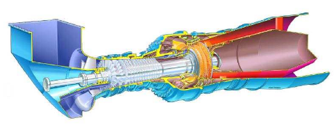
Figure 2.5. The sgt-800. The air intake, the compressor and the end of the shaft that can be connected to a generator are to the left in the figure. To the right the turbine and the exhaust are located
The sgt-800, seen in figure 2.5, has a single shaft which means that the compressor and the turbine operate on the same shaft. A generator can also be connected to the shaft via a gearbox. The first three vanes on the compressor can be adjusted, called variable guide vanes, vgv. The angle of the vanes can be altered so that they propel more or less air into the machine. This feature is used primarily to change the load of the machine. Once the gas turbine is synchronized to the electric grid the shaft must have a constant frequency.

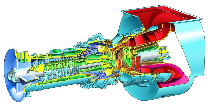
Figure 2.6. The sgt-700. To the left in the figure the air intake and the turbine are located. To the right the turbine, the exhaust and the shaft for connecting to the generator. Worth noting is that the turbine stages operate on different shafts
The sgt-700, seen in figure 2.6, is a dual shaft machine, with two adjustable guide vanes (called inlet guide vanes, igv ). The compressor and two turbine stages operate on the first shaft while the turbine and the generator, via a gearbox, operate on the second shaft. The compressor and the two turbine stages are called gas generator or gg and the turbine and generator are called power turbine or pt.
MODEL AND REGULATORS

Figure 3.1. The governing system for a power generation sgt-800 running on gas fuel only
Some, like the stc, are active a very limited time and some, like the flc, become active only when the turbine has reached its nominal speed. Figure 3.1 also shows how the input to the fuel valve controllers as well as the input to the variable guide vane controller is the output from other controllers. This means that the fuel valve controllers and the vgv controller function as actuators for the other control systems and need to be rather responsive to not cause poor performance of the entire regulator structure.
COMPUTATIONAL LOAD

Figure 4.1. The structure of the regulators analyzed for a power generation sgt-700 running on single fuel only
All the other regulators belong to OB 36 and are thus execute d every 30 ms. The structure of the regulators analyzed can be seen in figure 4.1 where it is clear how the regulators can be divided into two different kinds. The first kind calculates the needed heat flow for the machine and the second kind actuates valve and vane position. It is apparent that most of the regulators are of the first kind and only the pgfv, the mgfv, and the igv are of the second kind.

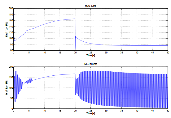
Figure 4.8. Demanded heat flow from the mlc when cycled with 30 and 100 ms. A step is added to the feedback of the regulator at time 20
The results for a cycle time of 30 ms and for 100 ms are seen in figure 4.8. It is rather clear that the regulator does not work well when cycled more slowly than 30 ms. The reason that the demanded heat flow does not climb up to the same level after the step as before is of course that the step remains active. The step works as a offset and makes the lo ad higher for the current heat flow than the model alone would.
RESULTS
The Simulator
The simulator for the sgt-800 works on a laptop using only Plcsim. It is a down-sized version of the program used to control the gas turbines. Logging of data has been removed to save computational load for the simulated plc and many signals used for measuring performance of the gas turbine have been removed. The simulator also suffers from short timeouts when the program is unresponsive
Result of the Analysis
When looking at the result for the analysis it is important to remember that it is a tradeoff between the amount of load that can be saved and the performance of the regulators, and in the end the performance of the complete gas turbine. When looking at the performance of the regulators for the different cycle times it does seem like it is possible to move many of the regulators to a cyclic interrupt with longer cycle time.
CONCLUSIONS AND FUTURE WORK
Conclusions
As the thesis was initiated with the aim to solve problems that did not exist the work of the thesis was split in two parts. As a result, neither of the two different parts in the thesis became very profound. In regards of the simulator there did not really exist that much more to do than to implement the simulator. Due to the limited time available not all the regulators could be analysied, as would have been the ideal, but the report still produced some suggestions on how load can be saved.
Even though Plcsim was not as limiting as first thought it is still not constructed to run as much code as currently done. This results in a situation where the fundamental performance of Plcsim sets the limits for the performance of the simulator. This situation is of course not good but a solution to the problem could to be to construct a new plc simulator able to run the amount of code necessary.
Future Work
Since Plcsim does not work well enough it would be a good idea to construct an simulator for a plc. When constructing the simulator focus should be on the ability to run large quantities of code. The work can be divided into several sub-sequent theses. For example a group of two master’s thesis students can be given the task to design and implement a simulator able to run quite much code. This can then be followed up by another master’s thesis student that can design and implement communication between simulated plcs. In this way Siemens would get a good alternative to in an easy way use simulated plcs to educate customers and staff.
Source: Linköping University
Author: Mikael Öijerholm
>> Simple Matlab Projects for EEE Final Year Students
>> Easy Microcontroller Project Ideas for Students
>> Huge List of Matlab Projects with Free Source Code
>> Matlab Project Topics List with Free Pdf for Mechanical Students
>> More Matlab Projects on Signals and Systems for Engineering Students
>> 200+ Matlab Projects based on Control System for Final Year Students
>> 80+ Matlab Projects based on Power Electronics for Engineering Students