ABSTRACT
Stereoscopy, a technique for creating the illusion of depth, has existed as early as the 1950s. With the ubiquity of smartphones, digital camera technologies has greatly advanced over the past decade. Although stereo cameras have existed for many years using film, there are few digital stereo cameras available. This project aims to build a portable, digital stereo camera using Raspberry Pis.
HARDWARE COMPONENTS
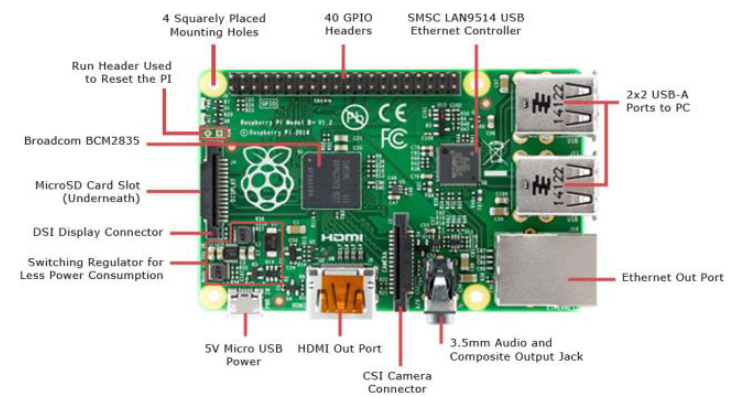
Figure 1: Raspberry Pi 2 Model B Diagram.
The Raspberry Pi is a credit card sized computer that was developed in 2006 to teach children how computers work. Although its primary function is to be an educational platform to teach programming to children, hobbyists, researchers, and engineers have adopted it to build small electronics projects due to its functionality and price. The Raspberry Pi 2 Model B, released in 2015, has a 900 MHz quad-core ARM Cortex-A7 CPU running Debian Linux. It has 1 GB onboard RAM, 40 GPIO pins, Camera Serial Interface (CSI) connector, 4 USB ports, and an Ethernet port.
CAMERA

Figure 2: Arducam Raspberry Pi Camera Module.
The Arducam Raspberry Pi camera module was used for this project. The camera module uses the OmniVision OV5647, a 5 megapixel sensor with a pixel size of 1.4 microns. It has an onboard lens with a fixed focus, and a maximum picture resolution of 2592 x 1944 pixels. It is capable of taking 1080p video at 30 frames per second. It is connected to the Raspberry Pi via the CSI interface. For this project, a picture and video resolution of 680 x 480 pixels was used for computational speed.
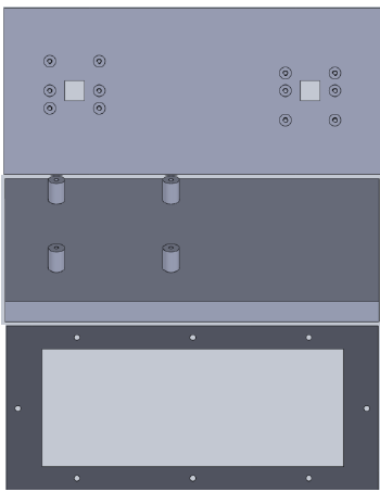
Figure 5: Enclosure Pieces.
A camera baseline of 10 cm was chosen for this project. The enclosure was 3D printed with polylactic acid (PLA) filament using a Makerbot Replicator 2. Figure 5 shows the front, top and bottom, and back pieces that make up the enclosure. The pieces are held together with M2 bolts.
PROCESSING STEPS
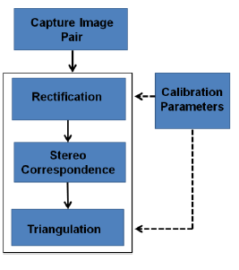
Figure 6: Outline of Processing Steps.
Once the images are captured from the device, they undergo the processing steps outlined in Figure 6:
Calibration
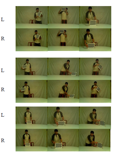
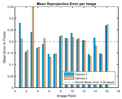
Figure 7: Calibration Images and Reprojection Errors.
A camera calibration method follows that outlined by Zhang and Heikkila and created for MATLAB by Bouguet. It uses a series of images with a checkerboard pattern at different areas in the camera’s field of view to determine camera pair’s intrinsic and extrinsic parameters. Figure 7 shows the 18 images used for calibration and their mean projection errors:
Image Rectification
The image rectification process has two steps: first, it removes the lens distortions that are measured from the calibration step. Second, the images are transformed such that they are coplanar. This applies the epipolar constraint to the stereo pair which enables a faster and more accurate stereo correspondence. The MATLAB function rectifyStereoImages() was used to perform the rectification
Stereo Correspondence
The Semi-Global Block Matching Algorithm outlined in (Hirschmüller, 2005) was used to compute the stereo camera’s disparity map. It uses a sum of absolute differences (SAD) similarity measure given by the following formula:

where Il and Ir denote the left and right image pixel grayscale values, w is the window size, i and j are coordinates of the center of the window for which the similarity measures are computed, and d is the disparity range.
Triangulation
Once the disparity map was computed, a triangulation step was done to project the position of the correspondence from pixel coordinates in the left image to three dimensional space. The MATLAB function reconstructScene() was used to perform this task.
EXPERIMENTAL RESULTS
The hardware was built and was successful in generating disparity maps of scenes under varied conditions. Figures 8-10 show images of the final hardware assembly: Images were retrieved from each Raspberry Pi via an Ethernet cable and the disparity map calculation was done offline on another computer running MATLAB.
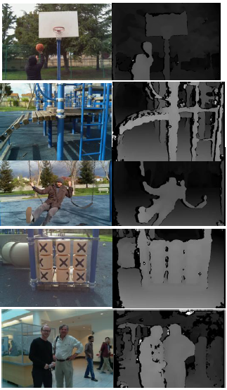
Figure 11: Left Camera Images and Disparity Maps.
The constructed stereo camera was tested indoors and outdoors to confirm its use in environments with varied lighting conditions. Figure 11 shows a collection of images taken from the left camera and the resulting disparity map from the pair of images.
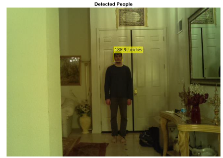
Figure 12: Example Image and Test Results.
Once an image was captured, the Viola Jones face detection algorithm was used to determine the pixel coordinates of the person’s face in the left camera image. Using the calculated disparity map of the stereo pair, the coordinates of the face’s centroid were projected in three dimensional space (as expressed in Section 3.4), and the physical distance was noted. Figure 12 shows an example image with the bounding box of the face detected with the corresponding measured real world distance.

Figure 13: Depth Accuracy Test Results.
As shown in Figure 13, the mean absolute error between the measured and actual distance was roughly 5.8 inches.
IMPROVEMENTS AND FUTURE WORK
A further improvement to this project would be to natively run the stereo vision algorithm on the Raspberry Pis. Although the computational time would drastically increase, the project would truly be standalone and portable. Utilizing the OpenCV library for Python would allow comparable functionality to that of the MATLAB functions used at this stage of the project. Adding a small touchscreen would also enable the user to see the disparity map on the device.
Furthermore, since we have two Raspberry Pis at our disposal, implementing a distributed computing architecture could provide the needed computational power to do the stereo algorithm onboard in an efficient manner.
ACKNOWLEDGEMENTS
I would like to thank Professor Gordon Wetzstein for teaching an amazing class. His encouragement and direction was instrumental in completing the project.
Source: Stanford
Authors: Aniq Masood
>> 50+ Matlab projects for Digital Image Processing for Engineering Students
>> More Matlab Projects on Video Processing for Final Year Students
>> Matlab Projects Fingerprint Recognition and Face detection for Engineering Students
>> 80+ Matlab Projects based on Power Electronics for Engineering Students
