INTRODUCTION
Problem Description
Unmanned Aerial Vehicle (UAV), or commonly known as drone, is a type of aircraft without a human pilot on board, as the name suggested, but controlled autonomously by computers and/or taking commands from remote stations. The UAVs are perfect candidates for tasks that are tedious or dangerous for human, for example, patrolling along boarder lines, wild fire control, aerial surveillance and etc. The applications of UAV, as described above, generally require long flight time and reliable power supply. However, current UAV designs utilizing traditional battery or fuel cells usually struggles to meet such requirement.
Objectives
This project aims to provide an innovative solution to this problem by introducing the current popular photovoltaic system into the UAV power system design. It focuses on the electrical system design and the product will be a platform for future development on solar powered UAVs. The design is to be modular for easy module upgrade and replacement.
The UAV has a vast variety of configurations. The type of UAV chosen for this project is quadrotor helicopter, or called quadcopter, for its benefit as being easy to configure and having space for solar panel placement. A prototype software flight controller will also be designed to be the interface between human and the electrical system.
System Block Diagram
DESIGN
Since the input voltage from the solar module is between 6V to 11V and the required output voltage is 12V with variations less than 8%, a boost converter is proposed. For a boost converter, the relationship between the input and output voltage is as follows:

where D is the duty ratio of gate control signal to the MOSFET switch.
A fully functional MPPT circuit buil t in the project is shown in Figure 3, where the top yellow box shows input voltage sensor and red box shows the input current sensor.

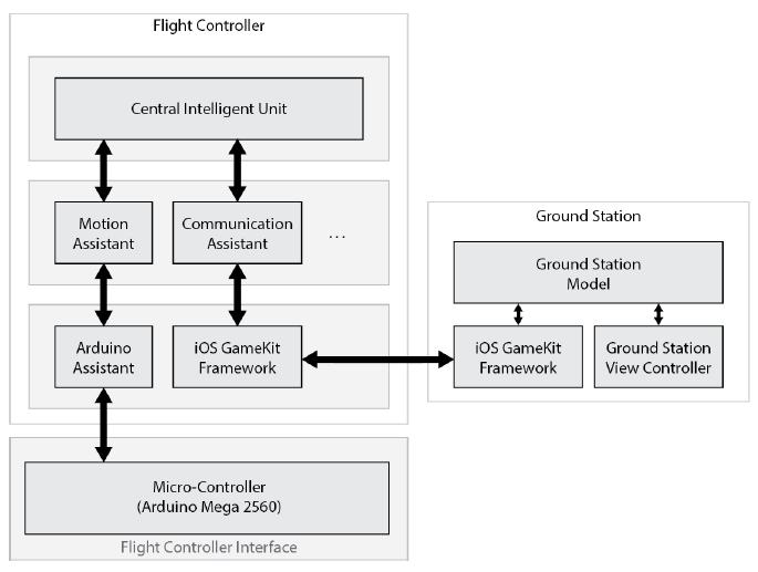
Figure 5 Flight Controller Block Diagram with Interface and Ground Station.
This prototype flight controller is built on iOS platform based on Objective-C language and is object-oriented. Four main objects are constructed till the date this report is written. They are Central Intelligent Unit, Motion Assistant, Communication Assistant and Arduino Assistant, as shown in Figure 5.
At the startup of the application, Central Intelligent Unit will be automatically allocated and initialized. Then it will allocate and initialize all the other three objects and connect them accordingly. All the objects operate independently while occasionally communicating with each other if necessary.
REQUIREMENTS AND VERIFICATIONS

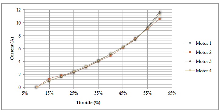
Figure 7 Current vs Throttle.
Figure 7 shows the current flowing into the ESC at 10% to 60% throttle. 4 motors behave almost the same with minor variations. Maximum current motor draws at 60% throttle is 11.7A.

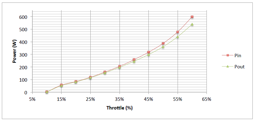
Figure 9 Power from battery vs power consume by motor.
This Figure shows power coming out from battery collected from reading of wattmeter and power consumed by four motors using P=VI.
COSTS

CONCLUSION
Accomplishment
A working power management system is designed, fabricated and tested in this project. Such power management system is able to prolong the flight time of quadcopter, as opposed to that with only battery on board. The electrical system is also designed and assembled for functionality testing. Besides, a prototype software flight controller is designed for future development.
Difficulties and Uncertainties
- Mounting solar panels onto the quadcopter is hard to achieve since solar panels are fragile and vulnerable, it is easy to cause damage to the solar panels.
- Currently, the best solar cells available in the market possess an efficiency of approximately 20%, which is only able to prolong the flight time.
- The PID system embedded in the quadcopter is hard to tune due to lack of modeling information for the.
Ethical Considerations
We abide to the IEEE code of Ethics in designing and testing the system as follows
- to accept responsibility in making decisions consistent with the safety, health, and welfare of the public, and to disclose promptly factors that might endanger the public or the environment;
- to be honest and realistic in stating claims or estimates based on available data.
- to seek, accept, and offer honest criticism of technical work, to acknowledge and correct errors, and to credit properly the contributions of others
- to avoid injuring others, their property, reputation, or employment by false or malicious action. Since each motor is able to spin at 11850 rpm at full throttle, it turns out to be very dangerous incase it lost control. So we start with using three motors to test the self20 balancing system and hangs the quadcopter to a rod to make sure it would not fly all around and cause damage.
Future Work
We have achieved most of goals we set at the beginning of the semester. There are still some issues regarding stability of the quadcopter. We need to set up a model for this system to model the behavior of in-flight characteristics of the quadcopter so that we will be able to find the right pole locations for the PID system. Since we used iOS as our developing language, we are able to build a platform for other developers to join us, who can contribute more features.
Source: University of Illinois
Authors: Jinming Zhang | Jie Wang | Yingkan Ni

