ABSTRACT
To take advantage of the high speed in an optic fiber, one of the basic concept in fiber optic communication is to allow several users to simultaneously transmit data over the channel. One technique that provides multiple access is it fiber optic-code division multiple access (FO-CDMA). In FO-CDMA each user is assigned one or more signature sequences called codewords, which are subsets of a type of optical orthogonal code (OOC). The channel input/output consists of the superposition of several users codewords and at the receiver end an optical correlator extracts the information.
In the parallel code constructions, presented in this report, each user j is assigned a subset Cj from a code C. The subsets are disjoint and their union is the whole set C. A new way to map the information bits is to insert up to L zeros before each codeword from Cj and let this represent information as well. This gives high rates for active users but an investigation is needed to ensure that this does not compromise the systems wanted property of sending information with a small probability of errors for all users. Therefore a simulation environment has been implemented in Matlab.
The result from these simulations shows that BER for the L parallel codes is acceptable and not much higher than for the traditional constructions. Because of the higher rate these construction should be preferred but an analysis if a hardware implementation is possible.
FIBER OPTIC COMMUNICATION

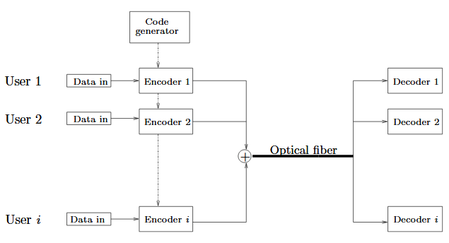
Figure 2.1. A FO-CDMA system with i users
Fiber optic code-division multiple access (FO-CDMA) is one technique to allow several users to transmit simultaneously over the same optical fiber. A FO-CDMA system can, for each user, be described by a data source, containing the data that will be sent, followed by an encoder and then a laser that maps the signal from electrical form to an optical pulse sequence. At the receiver end an optical correlator is used to extract the encoded data.
In this report we will consider the system to be chip synchronized, that is all users chip durations (pulse widths) are of equal lengths and when creating the superposition of chips they overlap each other precisely. Of course the users can be delayed relative each other. Figure 2.2 on the next page shows an example of how the bits are encoded and the superposition of the users codewords that are sent over the channel. Here user 1 is delayed with 3 chips relative user 2.

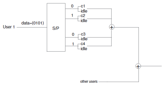
Figure 2.3. Example of ordinary parallel code. User 1 is assigned four codewords and sends the message (0,1,0,1)
If a user is assigned one codeword of length n it means that n chips will carry one information bit. However some users require higher rate and are therefore assigned more codewords. If a user is assigned K codewords we can encode a block of K information bits onto n chips and we call this costruction ordinary parallel code. As an example (see figure 2.3) we consider a user having K = 4 codewords (c1, c2, c3, c4) and will send the message m1 = (0,1,0,1).
L PARALLEL CODE

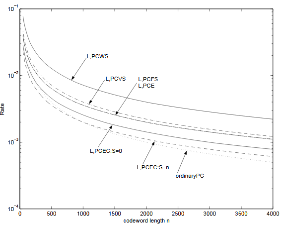
Figure 3.3. Rate as a function of codeword length n. L is chosen for maximum rate for every value of n. Codewords assigned to each user is K = 2
As one can see the rate for the L parallel code constructions is greater than K/n if L is chosen properly. Note also the similarity between L, P CF S and L, P CE which have almost the same rate. In the figure below rate is plotted as a function of the codeword length n and L is chosen for maximum rate for every value of n.
MATLAB IMPLEMENTATION OF THE L PARALLEL CODE SCHEMES

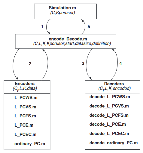
Figure 4.1. Overview of the Matlab functions. The sequence 1 to 5 is done several times to create a mean value from every simulation
When all input parameters are specified, the program starts a loop from i=minUsers to i=maxUsers. To be able to create a mean value, several simulations from encode − Decode.m are used for every such i. Which i users that will be active for every simulation is random selected. All results from this i are added together and BER is calculated. Also the idle mode errors is added together.
When all different number of active users have been simulated the result is shown on the screen and BER as a function of number of active user is plotted. The number of idle mode errors is plotted as a function number of not active users.
RESULTS AND CONCLUSIONS
The L parallel codes should be able to use codes with aperiodic correlation and it is interesting to know how the performance depends on the choice of code. The codes used for the simulations are:
OOC: The parameters for this optical orthogonal code is λ = 1, w = 4, cardinality | C | = 28 and codeword length n = 337.
AOOC: This acyclic optical orthogonal code has the following parameters, λ = 1, w = 4, cardinality | C | = 28 and codeword length n = 229.
They are created to have the same weight and cardinality to be comparable to each other. The first investigation is to simulate the systems capacity, that is how the systems performance depends on the number of active users.
Source: Linköping University
Authors: Shi-Yun Kang | Hsiang-Chih Wen
>> Simple Matlab Projects for EEE Final Year Students
>> Top 50+ MATLAB based Simulation Mini Project Topics & Final Year Project Titles for ECE Students
>> MATLAB Project Ideas and Titles for Electrical & Electronics Engineering Students
>> More Matlab Projects on Signals and Systems for Engineering Students
