ABSTRACT
Accumulator Volume Sensing Team has developed two sensor designs aimed at detecting the position of the piston within a 4024 accumulator. The two designs include the use of a Renishaw LMA10 magnetic encoder and a SpectraSymbol HotPot linear potentiometer.
The magnetic encoder solution drastically increases the accuracy of sensing the piston position compared to the current solutions of both a string-pot and linear variable differential transformer while costing slightly less. The linear potentiometer seeks to provide a solution that drastically decreases the cost compared to the present sensing methods. Both designs call for a modification to one half of the piston guide part on the 4024 piston accumulator.
The purpose of this report is to outline the design process we went through in selecting our two final solutions, as well as explain how we propose the sensors be implemented in an accumulator. Also included is the testing process and resulting accuracy uncertainty. This project covers both the mechanical design of the sensor mounting, as well as the electrical signal processing or adjustment.
BACKGROUND
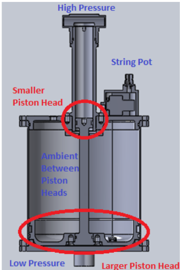
Figure 4.1. – Bootstrap 4024 Fluid Accumulator
PDT designs several different types of accumulators including piston/spring, bellows, and bootstrap. AVST aimed to develop a sensor using a bootstrap accumulator as reference due to the availability and ease of implementation. A bootstrap accumulator utilizes two cylindrical chambers of different cross-sectional areas connected by a piston as seen in Figure 4.1. A high pressure source sits in the smaller chamber while the low pressure coolant resides in the bigger chamber.
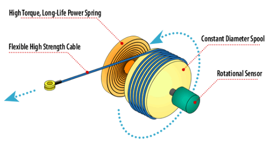
Figure 4.2. – Components of a String Potentiometer
A string potentiometer consists of a cable wound around a spool. The spool is attached to both a torsion spring and a rotational sensor. As the end of the cable is pulled, the spool spins along with the sensor, translating linear motion into rotary motion which effects an electrical output. The torsion spring keeps the cable in tension allowing the spool to spin the other direction as the cable retracts and winds back up. Figure 4.2 shows the components of a string-pot. In an accumulator, the string-pot is mounted outside on top of the housing, with the end of the cable attaching to the piston.
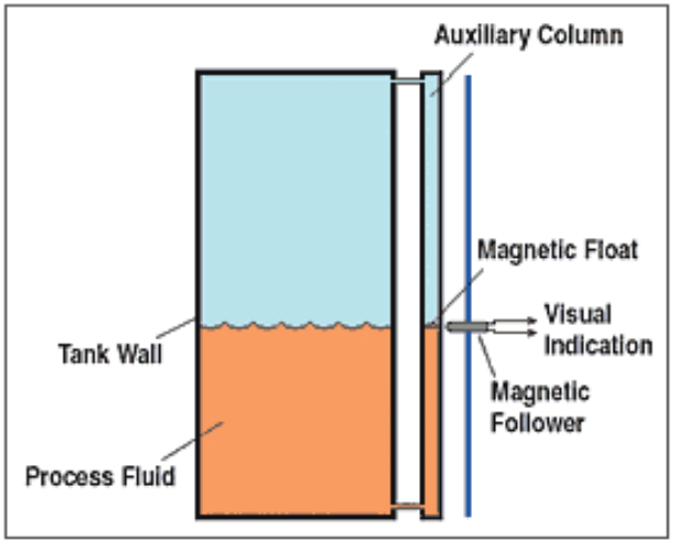
Figure 4.5. – Magnetic Level Sensor Basics
Because sensors are commonly used in multiple fields of engineering, the team quickly realized that there are many alternative solutions to the string-pot or LVDT. One method that AVST came across is a magnetic level gauge. As seen in Figure 4.5, a magnetic fol- lower is coupled to a float or piston. The magnetic follower can then be used as a visual indicator in conjunction with a linear reference. This method would be helpful in finding the piston’s position an auxilary fluid column was incorporated onto the accumulators design.
REQUIREMENTS
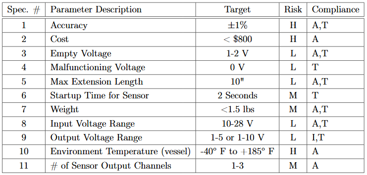
Table 5.1. – Engineering Specifications for Accumulator Volume Sensor

Table 5.2 contains a key for the abbreviations used
Currently, the LVDT incorporates redundancy through the utilization of two sensor channels. This means the same physical measurement is obtained twice by the sensor. The team would like to implement redundancy due to the high safety priority associated with aerospace applications. We have specificied a redundancy specification of 1-3 channels in Table 5.1. Two channels would be most desired if possible due to the conflicting interest of space and redundancy.
DESIGN DEVELOPMENT
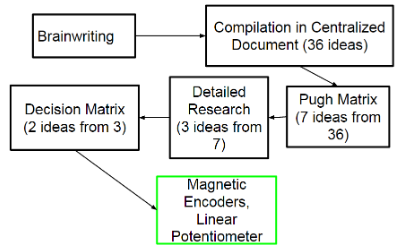
Figure 6.1. – Concept Design Process
Over the course of several weeks, the team held numerous brainstorming sessions in order to generate an extensive list of solutions. The favored approach during this time was the brain-writing method. This is a method where team members brainstorm a few ideas, then elaborate on each other’s to discover different aspects of a potential design. The ideas in Figure 6.1 helps to visualize our concept selection process.
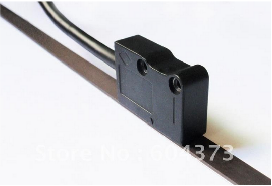
Figure 6.8. – Example of a Magnetic Encoder
A linear magnetic encoder (as seen in Figure 6.8) utilizes a magnetic strip with a line of alternating poles attached along the length of the piston. A magnetic sensor called a “readhead” would be mounted stationary next to the piston (within a few millimeters). As the piston moves upwards or downwards, the alternating poles would be detected by the readhead and be output most commonly as a digital signal, although some direct analog solutions exist with programming of the sensor.
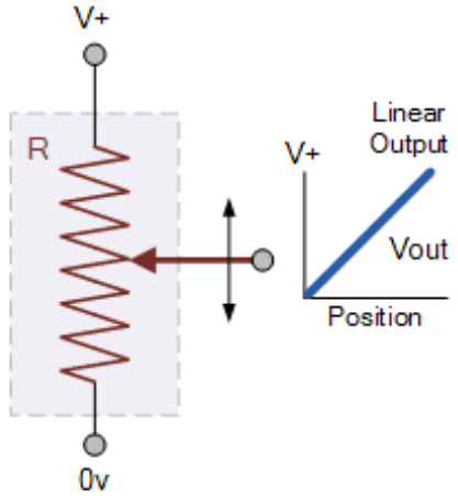
Figure 6.12. – Electrical Diagram of a Linear Potentiometer
The force of the plunger connects the wiper layer and the resistive strip together. Depending on where the strip is pressed, the effective resistance the current has flown through changes, allowing the wiper to probe the continuous voltage drop anywhere along the strip. In this con- figuration of a potentiometer, the output voltage varies based on the location of contact with the plunger. The underlying principle of a linear potentiometer is shown in Fig 6.12.
DESCRIPTION OF FINAL DESIGN

Table 7.3. – The two options available for obtaining the encoder output
It is important to note that PDT had stated that they are not concerned with how the output of the encoder is obtained, and that it should function mostly as a proof of concept. Thus, the two options shown in Table 7.3 consist of either a bus analyzer or a micro-controller. Figure 7.9 shows the proposed scheme for either option. Preparing the chosen option for the output of the encoder was done during the manufacturing stage, and was further iterated to faultlessness during the testing stage.
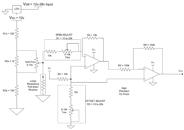
Figure 7.10. – Proposed circuit for obtaining the position output of the linear potentiometer, as well as perform adjustments for offset and span on it
The output of the linear potentiometer can be obtained through the use of a voltage divider circuit. This circuit is shown in Figure 7.10. The calculations justifying the choice of resistance values and usage of op-amps are shown and explained in detail in Appendix D.7. The resistance values were tuned by math and plotting the output voltage in MATLAB. From there, numerous resistance values were varied methodically until a trend was seen in how the adjustment of a resistance value effected the output voltage of the circuit.
DESIGN VERIFICATION
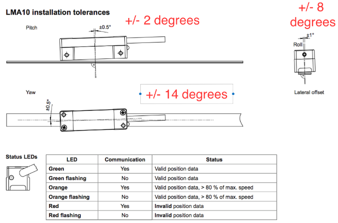
Figure 8.3. – Re-established Magnetic Encoder Installation Tolerances
The data sheet claims sensitive tolerances to changes in pitch, yaw, and roll of the encoder with respect to the magnetic strip. However, through our benchtop assembly we found that the magnetic encoder was still functional even past the tolerances shown in Figure 8.3. This is verified by the encoder’s LED remaining green, signaling a valid sensor reading. Furthermore, we found the rough approximate limits of the angle tolerances highlighted red in Figure 8.3. These tests were done using feeler gauges to offset the encoder by a certain angle on one side until the encoder’s LED toggled from green to red signaling an invalid reading
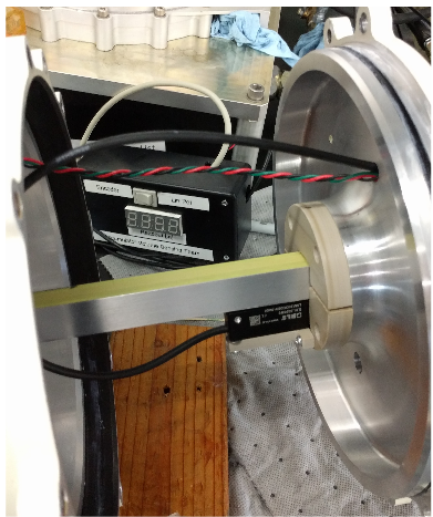
Figure 8.5. – Posistion Sensors Integrated onto the 4024 accumulater at PDT
Once the sensors were implemented into 4024 accumulator, we ran a one direction test by increasing pressure on the high pressure side of the accumulator. As the piston moved, we took position measurements of both sensors and compared them against caliper mea- surements. Results of this test can be viewed in Figure 8.6. The results verify that the sensors are mechanically functional within the accumulator.
PRODUCT REALIZATION
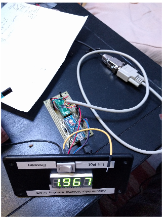
Figure 9.6. – The final product of the electronics manufacturing, the proto-board
The design was first verified on the breadboard, then transferred to a proto-board. The proto-board is shown in Figure 9.6 where the same circuitry as the breadboard can be seen on the protoboard, as well as the additions of a display and switch. This was added to the design to make the final product a uniform interface between the linear potentiometer readings and the encoder readings.
CONCLUSIONS AND RECOMMENDATIONS
To conclude this design report, AVST hopes that our solutions will save PDT money, and improve their current accumulator designs. Although this design report focused on the 4024 accumulator for testing, we hope that PDT might be able to implement our solutions in other accumulators as well.
For the encoder, we recommend that PDT utilize a micro-controller solution so that the digital output may be processed and sent where it is needed. The driver code written for the IC-MB4 took a substantial amount of time, and we encourage PDT to make use of the IC-MB4 driver library written by us. This will save a significant amount of development effort.
Furthermore, we would like to note that the encoder provided resolution that far exceeds the requirements of PDT. As a result, we encourage PDT to question whether the encoder solution would be cost-effective for their application. We also suggest that the encoder solution be used to improve the calibration process for their existing position measurement solutions or for calibrating the linear potentiometer. The encoder serves as an exceptional baseline measurement device.
We believe that the linear potentiometer holds the most potential for PDT due to its extremely low cost. The sensor achieved a +/- 0.06 inch accuracy using a linear calibration, and a +/- 0.03 inch accuracy using a cubic calibration. The drastic reduction in cost per sensor is appealing and would be a welcomed change during assembly into the accumulator due to it’s simplicity.
Source: California Polytechnic State University
Authors: Chris Naughton | Kinwei Yu | Michael George
>> Simulink Projects using Matlab for Engineering Students
>> Simple Matlab Projects for EEE Final Year Students
>> 50+ Matlab projects for Digital Image Processing for Final Year Students
