ABSTRACT
In this project, a sensor-less system has been developed for an induction machine in railway applications. The approach which was taken in this project thesis is a consequence of the expectations of the company: investigate the possibilities of having the current generation of Alstom’s drive system working without use of a speed sensor. Some tests have thus been performed in order to validate parts of this statement.
However, because of the substantial time that would require an exhaustive investigation and a complete development, from simulation to tests on a real train, it has been decided to focus more on selecting a method relevant for Alstom’s specications, and simulate it in order to identify issues.
Thus, from an extensive literature search based on books and articles considered as references, several methods has been investigated and one have been selected for simulation. Two set-ups were used for simulations; one developed in MATLAB and the other one using real-time simulators used by Alstom to test and validate its hardware and control software.
From these tests, it was showed that for an accurate control, it is necessary to estimate, jointly with the speed, main motor parameters. But these motor parameters can hardly be all estimated at the same time and a strategy in order to estimate efficiently these other parameters is proposed. Issues related to a practical implementation are also investigated and some conclusions are drawn for an implementation of a sensor-less system in an Alstom train.
EXTENDED KALMAN FILTER
A brief introduction of the EKF has been done in section 2.2.1. A physical, non-linear system can be described with the following equations.

In (3.1.1) and (3.1.2), x is the state vector, u and y are the input and output vector respectively, f is the function of the inputs and states and h is the function of the outputs.
SIMULATION

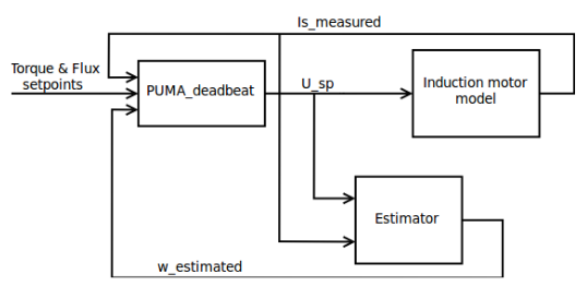
Figure 4.1: Schematic diagram of the simulation setup
Concerning the speed estimator, the aim was to use it with an existing control algorithm, and thus the estimated speed of the estimator was fed to the control algorithm as if it was the measured speed (see Figure 4.1). The main reason which lead to this design was that it would have been time-consuming to develop a completely sensorless control algorithm. Another advantage of this method is that it’s very simple to switch between the estimated speed and the measured speed.

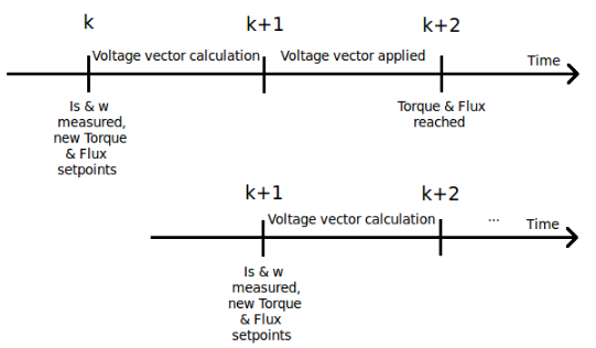
Figure 4.2: PUMA deadbeat behaviour
This controller is given the desired torque and magnetization at a time k, the state of the motor (current from sensors) also at the time k, do a prediction of the state of the motor at time k + 1 (motor speed is considered constant), calculate the voltage vector to apply to the motor at time k + 1, and apply it from time k + 1 to time k + 2, in order to reach the desired torque and magnetization at time k + 2 (see Figure 4.2).

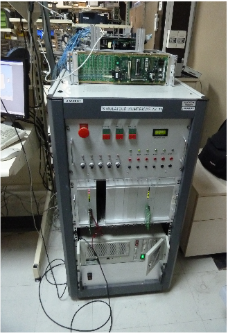
Figure 5.1: SITRA 1 simulator
SITRA 1 is the first generation of SITRA simulators. These real-time simu- lators simulate the induction machine and power electronics, and are used to test complete traction control (both software control and hardware control) in conditions close to the reality. The inputs of the traction control are torque and flux set points from the supervisor, sensor measurements (current, filter voltage, motor speed) from the train and the outputs are PWM signals sent to the power electronics of the train which drive the motors.
For the problem of the initial speed, Figure 4.30a do not give an optimal answer. An optimal point would give, for a specific initial estimator speed, low mean produced torque at every speed. However, Figure 4.30b gives an interesting result. Some points do not appear on the curve, which means that the estimator has not converged (i.e. the control algorithm has failed to magnetize the rotor with the given initial considered speed). It seems that having an overestimated initial speed is easier to handle for the algorithm than an under- estimated initial speed, and that the only initial speed which could guarantee a magnetization of the rotor at every speed (and specially at the maximal speed) is the maximal speed.
Source: KTH
Author: Vincent Ardiet
>> Huge List of Matlab Projects with Free Source Code
>> Simple Matlab Projects Base Papers for Engineering Students
>> Top 50+ MATLAB based Simulation Mini Project Topics & Final Year Project Titles for ECE Students
>> 200+ Matlab Projects based on Control System for Final Year Students
>> 80+ Matlab Projects based on Power Electronics for Engineering Students
