ABSTRACT
A circuit breaker is an automatically operated electrical switch designed to protect an electrical circuit from damage caused by overload or short circuit. Its basic function is to detect a fault condition and interrupt current flow. Unlike a fuse, which operates once and then must be replaced, a circuit breaker can be reset (either manually or automatically) to resume normal operation.
When operated manually we see fatal electrical accidents to the line man are increasing during the electric line repair due to the lack of communication and coordination between the maintenance staff and the electric substation staff.
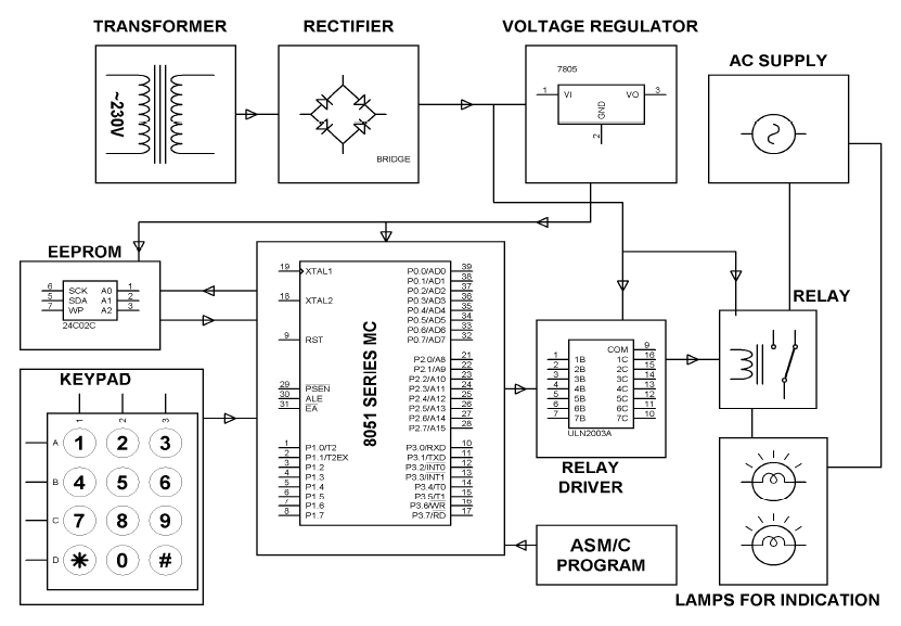
In order to avoid such accidents, the breaker can be so designed such that only authorized person can operate it with a password. Here, there is also a provision of changing the password. The system is fully controlled by the 8 bit microcontroller of 8051 family. The password is stored in an EEPROM, interfaced to the microcontroller and the password can be changed any time unlike a fixed one burnt permanently on to the microcontroller. A keypad is used to enter the password and a relay to open or close circuit breaker, which is indicated by a lamp. Any wrong attempt to open the breker (by entering the wrong password) an alert will be actuated, indicated by another lamp.
DESCRIPTION
A resistor is a two-terminal electronic component designed to oppose an electric current by producing a voltage drop between its terminals in proportion to the current, that is, in accordance with Ohm’s law: V = IR.
A capacitor or condenser is a passive electronic component consisting of a pair of conductors separated by a dielectric. When a voltage potential difference exists between the conductors, an electric field is present in the dielectric.
PRINCIPLE
The main component in the circuit is 8051 microcontroller. In this project 4×3 keypad is used to enter the password. The password which is entered is compared with the predefined password. If entered password is correct then the corresponding electrical line is turned ON or OFF. In this project a separate password is provided to each electrical line. Activation and deactivation of the line (circuit breaker) is indicated by the load.
WORKING
The circuit uses standard power supply comprising of a stepdown transformer from 230Vto 12V and 4 diodes forming a bridge rectifier that delivers pulsating dc which is then filtered by an electrolytic capacitor of about 470μF to 1000μF. The filtered dc being unregulated, IC LM7805 is used to get 5V DC constant at its pin no 3 irrespective of input DC varying from 7V to 15V.
The input dc shall be varying in the event of input ac at 230volts section varies from 160V to 270V in the ratio of the transformer primary voltage V1 to secondary voltage V2 governed by the formula V1/V2=N1/N2. As N1/N2 i.e. no. of turns in the primary to the no. of turns in the secondary remains unchanged V2 is directly proportional to V1.
OPERATION

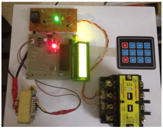
Fig: CB in closed state shown by green LED.

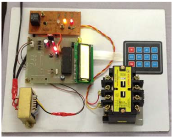
Fig: CB in open state shown by red LED.
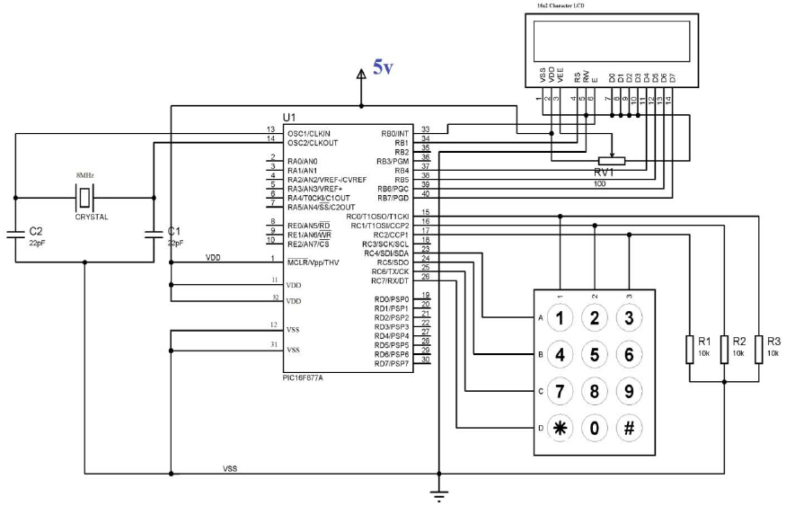
For the operation of circuit breaker through a password, program is written in keil software and created into a .hex file that is further burnt onto the controller with the help of flash magic. Connections are given as per the circuit diagram. While giving the connections, it should be made sure that there is no common connection between AC and DC supplies.
CONCLUSIONS
The project titled ‘ELECTRIC LINEMAN SAFETY BY USER CHANGEABLE PASSWORD BASED CIRCUIT BREAKER’ gave the following conclusions.
- It can work on a single given known password
- The password to operate can be changed and system can be operated efficiently with the changed password
- No other person can reclose the breaker once the changed password is given into system other than the person who had changed it.
- It gives no scope of password stealing
- It is effective in providing safety to the working staff
- It is economical
- It can be easily installed.
Source: Techinical Research Organisational India
Authors: J.Veena | G.Srivani | Afreen | M.Sunil Kumar | J.Santhosh | K.B.V.S.R.Subrahmanyam

