ABSTRACT
With advances in solid-state power electronic devices and microprocessors, various pulse-width-modulation (PWM) techniques have been developed for industrial applications. For example, PWM-based three-phase voltage source inverters (VSI) convert DC power to AC power with variable voltage magnitude and variable frequency.
This thesis discusses the advantages and drawbacks of three different PWM techniques: the sinusoidal PWM(SPWM) technique, the third-harmonic-injection PWM(THIPWM) technique, and the space-vector PWM (SVPWM) technique. These three methods are compared by discussing their ease of implementation and by analyzing the output harmonic spectra of various output voltages (poles voltages, line-to-neutral voltages, and line-to-line voltages) and their total harmonic distortion (THD).
The simulation results show that both the THIPWM and SVPWM techniques have lower total harmonic distortion than the SPWM technique. The THIPWM and SVPWM techniques in the under-modulation region can both increase the fundamental output voltage by 15.5% over the SPWM technique. Moreover, the SVPWM technique can increase the fundamental output by about 5% in each of the overmodulation regions 1 and 2, respectively.
SINUSOIDAL PWM AND THIRD-HARMONIC-INJECTION PWM
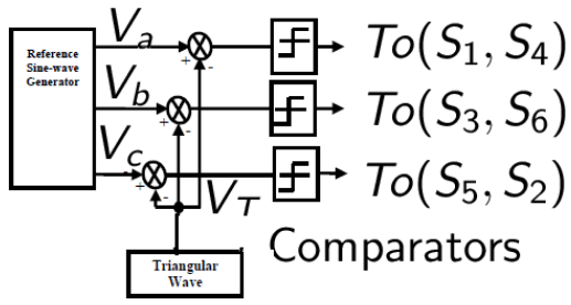
Figure 2.1: Control Signal Generator for SPWM
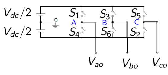
Figure 2.2: Three-Phase Sinusoidal PWM Inverter
A six-step inverter is composed of six switches S1 through S6 with each phase output connected to the middle of each inverter leg as shown in Figure 2.2. The output of the comparators in Figure 2.1 form the control signals for the three legs of the inverter. Two switches in each phase make up one leg and open and close in a complementary fashion. That is, when one switch is open, the other is closed and vice-versa.
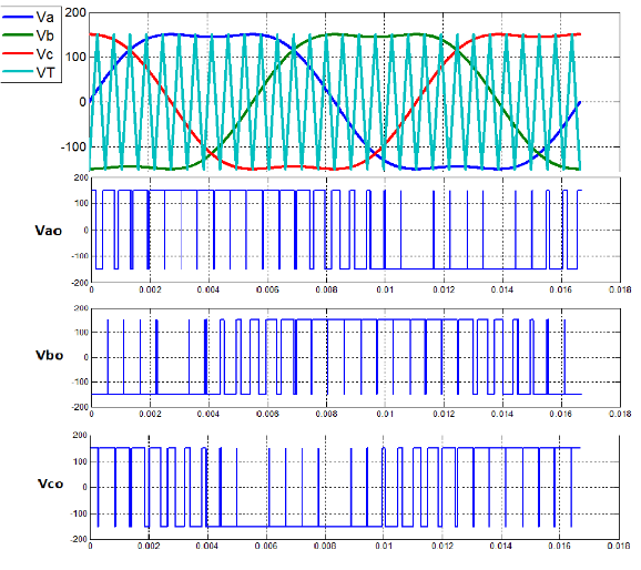
Figure 2.5: Reference Voltages (a,b,c), Triangular Waveforms ( VT ), and Output Voltage ( Vao, Vbo, Vco )
The THIPWM is implemented in the same manner as the SPWM, that is, the reference waveforms are compared with a triangular waveform. As a result, the amplitude of the reference waveforms do not exceed the DC supply voltage Vdc/2, but the fundamental component is higher than the supply voltage Vdc. As mentioned above, this is approximately 15 . 5% higher in amplitude than the normal sinusoidal PWM. Consequently, it provides a better utilization of the DC supply voltage. The three reference voltages and triangular waveform of a three-phase THPWM produce the following output pole voltages Vao, Vbo, Vco shown in Figure 2.5.
SPACE VECTOR PWM
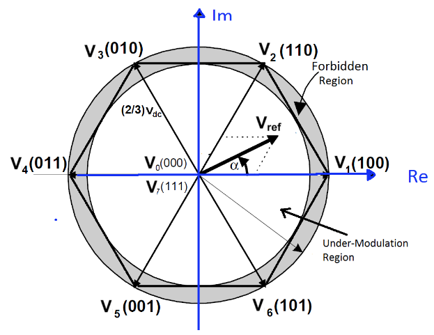
Figure 3.1: Under-modulation and Over-modulation Regions in Space Vector Representation
SVPWM is accomplished by rotating a reference vector around the state diagram, which is composed of six basic non-zero vectors forming a hexagon. A circle can be inscribed inside the state map and corresponds to sinusoidal operation. The area inside the inscribed circle is called the linear modulation region or under-modulation region. As seen in Figure 3.1, the area between the inside circle and outside circle of the hexagon is called the nonlinear modulation region or over-modulation region.
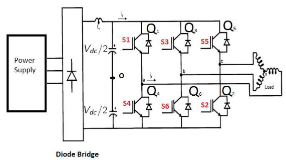
Figure 3.2: Three-Phase Bridge Inverter
The basic principle of SVPWM is based on the eight switch combinations of a three- phase inverter. The switch combinations can be represented as binary codes that correspond to the top switches S1, S3, and S5 of the inverter as shown in Figure 3.2. Each switching circuit generates three independent pole voltages Vao, Vbo, Vco which are the inverter output voltages with respect to the mid-terminal of the DC source marked as ‘O’ on the same figure. These voltages are also called pole voltages.
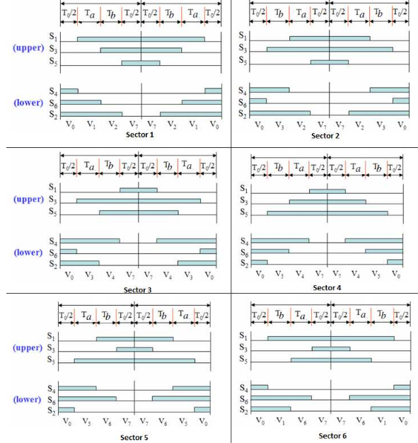
Figure 3.11: Switching Sequence of all Six Sectors
The switching pulse patterns of six different sectors in Figure 3.11 are shown for the upper and lower switches of a three-phase inverter. It is obvious that in the odd sector the active state sequence is in ascending-descending order; whereas, it is in a descending- ascending order in an even sector.
SPACE VECTOR PWM IN OVER-MODULATION REGION
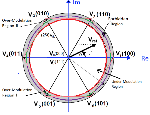
Figure 4.1: The Two Over-Modulation Regions in Space Vector Representation
The modulation index of the over-modulation region ranges from 0.907 up to 1. The over-modulation range can be considered as one region or it can be divided into two regions (see Figure 4.1). In this thesis, the over-modulation region is considered as two regions with two modes of operation depending on the modulation index values.
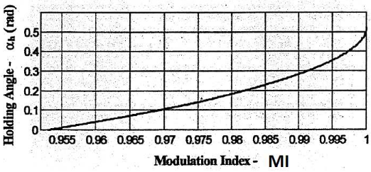
Figure 4.5: Holding Angle vs. Modulation Index in Mode 2
At the end of mode 1, the component of the reference voltage changes to a piecewise linear waveform. When the modulation index is higher than 0.952, the second region of the over-modulation region algorithm is entered. Both the reference magnitude and the phase angle have to be changed compared to the linear region. The modified reference vector is held at a vertex of the hexagon in every sector for the rest of the switching period. The angle for which the active switching state vector is held constant is called the holding angle αh. Figure 4.5 shows the holding angle in region 2 as a function of the modulation index.
SIMULATION RESULTS
SPWM is very popular and easy to implement using comparators. The SPWM simulink system model is built in Figure 5.1. It has the following blocks: (1) Sinusoidal wave generators, (2) High-frequency triangular wave generator, and (3) comparators. he SPWM technique treats each modulating voltage as a separate entity that is com- pared to the common carrier triangular waveform. A three-phase voltage set ( Va, Vb, and Vc ) of variable amplitude is compared in three separate comparators with a common triangular carrier waveform of fixed amplitude as shown in the same figure.
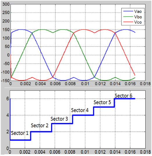
Figure 5.16: Vao, Vbo and Vco for Linear Modulation SVPWM after Filtering
Figure 5.16 shows the output voltage waveforms obtained from the SVPWM strategy. The modulation waveform of the seven-segment SVPWM has a saddle shape when passed through a low-pass filter (Figure 5.16) and its line-to-neutral voltages are sine waveforms because of the under-modulation PWM region (Figure 5.17). The maximum neutral voltages Van, Vbn, and Vcn in Figure 5.18 is Vdc /√ 3 (173.2 Volts).
COMPARISON BETWEEN SPWM, THIPWM, AND SVPWM TECHNIQUES
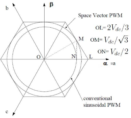
Figure 6.1: Locus Comparison of Maximum Peak Voltage in SPWM and SVPWM
The simulation studies of Chapter 5 confirmed that the THIPWM and SVPWM techniques have a better DC bus voltage utilization than SPWM. As seen in Figure 6.1, the smaller circle represents the operating region of the SPWM technique and the larger inscribed circle represents the operating region of the SVPWM technique in the under-modulation region.
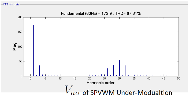
Figure 6.10: Spectrum of Vao in The Under-Modulation Range of SVPWM

Table 6.4: V ao in Over-Modulation Region 1 of SVPWM
Figure 6.10 and Table 6.4 show the harmonic results of Vao in the over-modulation region 1 of SVPWM. Overall, the spectrum of this technique is similar to the under-modulation of SVPWM. However, it has a higher fundamental voltage and a higher value of the 3rd harmonic. We also see additional harmonic values around the carrier frequency (30th harmonic) and a lower THD (%) with a higher modulation index.
CONCLUSION AND FUTURE WORK
Conclusion
This thesis has evaluated three different PWM techniques, namely SPWM, THIPWM, and SVPWM (in the linear modulation region and over-modulation mode 1). The contributions of the thesis are as follows:
- The thesis has provided a thorough review of the each techniques with a special focus on the operation of SVPWM in the under-modulation and over-modulation modes.
- In this thesis, Simulink models for all three techniques have been developed and tested in the MATLAB/Simulink environment. The SVPWM model is able to generate both the operation of the under-modulation region of SVPWM as well as the over-modulation region 1.
- The thesis discusses the advantages and drawbacks of each technique. Their simulation results are compared and analyzed by plotting the output harmonic spectra of various output voltages, and computing their total harmonic distortion (THD).
Recommendations for Future Work
There are couple of interesting topics suggested for future research:
- Further simulation studies should be performed in region 2 of over-modulation SVPWM with neural networks and The Neural Network toolbox of MATLAB. Neural network implementation is very fast and can increase the switching frequency of power switches in the inverter.
- Many papers in the literature have reported that the dead time of space vector PWM has an influence on drive systems. To circumvent this problem, it is important to research how to compensate for the dead time effect in order to increase the performance of drive systems.
Source: Boise State University
Author: Phuong Hue Tran
>> Simulink Projects using Matlab for Engineering Students
>> Simple Matlab Projects for EEE Final Year Students
>> More Matlab Projects on Signals and Systems for Final Year Students
>> 200+ Matlab Projects for Control System for Final Year Students
