ABSTRACT
Asynchronous machines are considered nowadays the most commonly used electrical machines, which are mainly used as electrical induction motors. Starting the induction motor is the most important and dangerous step.
The theory behind this project is based on representing the real motor by a set of equations and values in MATLAB using the subsystem feature, forming a corresponding idealistic motor in a way where all the physical effects are similar.
Starting the induction motor is the most important and dangerous step, where the motor properties play a major role in the evaluation of all electrical motors, and these properties are defined by the following factors:
- Starting torque
- Starting current
- Transient state
- Smoothness of the starting
- Simplicity and economics of starting
The motor is started under different loads in two methods: Direct and Soft starting. Each method is studied and discussed using supporting simulation of currents, torque, speed, efficiency and power factor curves.
A GENERAL OUTLINE OF INDUCTION MOTORS
The 3ph Induction Motor Structure
A. Stator
The stator is formed from thin plates with a thickness of (0.35 – 0.5 mm ) of Ferromagnetic iron. These plates are painted before being assembled with insulating materials to reduce Eddy currents losses. The inner part of the stator has a cylindrical shape filled with insulated copper inductors that form the stator windings. These windings form a balanced three – phase circuit connected in either star or delta formation.
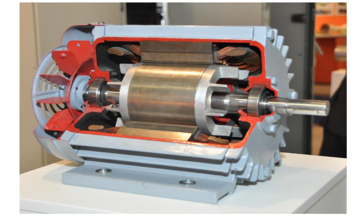
Figure 2 .1 Induction motor structure
B. Rotor
This part is also formed from thin plates of Ferromagnetic iron assembled together to form a cylindrical shape which has slots on its outer surface. As in the stator, the rotor coils can also be a three – phase circuit or a multi – phase circuit. The endings of the phases of the rotor coils are connected in star formation and fixed on the axis of the machine. Rotors are sorted in terms of the type of its coils into two types Squirrel cage Rotor and Slip Ring Rotor.
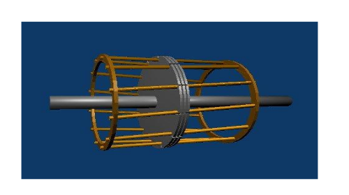
Figure 2.2 A square cage rotor
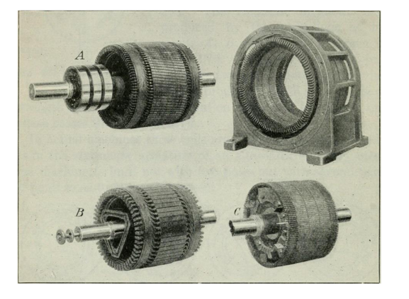
Figure 2.3 Different kind of rotors
THE GENERAL THEORY OF ELECTRICAL MACHINES
This theory is based on representing the real machine with a corresponding idealistic machine in a way where all the physical effects are similar. This idealistic machine is symmetrical (has two poles and two phases) and has two pairs of identical windings on perpendicular axes in both the stator and the rotor. The windings are fed by two AC currents that are shifted by (90°) from each other according to time as shown in Figure (3.1) The idealistic machine is treated as a two poles machine because the magnetic flux distribution is repeated after each pair of poles, no matter how many poles there are in the real machine.
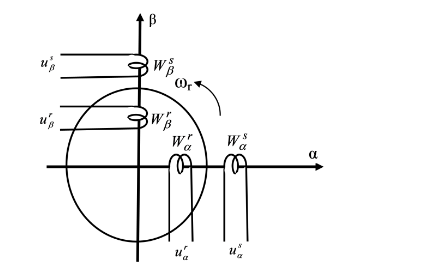
Figure (3.1) The ideal machine circuit
SIMULATING AND STARTING THE 3PH INDUCTION MOTOR IN MATLAB
In order to simulate the induction motor in Matlab, the following steps are done.
A. The induction motor model
B. Simulating starting curves in No-load\Load cases
C. Direct starting method
SOFT STARTING METHOD
This method is implemented by gradually increasing the voltage applied on the induction motor, starting from a certain value up to the nominal voltage of the motor. The process of increasing the voltage gradually is performed by a three phase thyristor ac voltage regulator. The regulator consists of six thyristors – two for each phase-that are connected to the motor as shown in figure (5.1). The voltage of the motor can be adjusted by modifying the pulses triggering angles, which are applied on the thyristors gates. The certain voltage value applied on the motor is experimentally found. It is the least value the motor could start at.
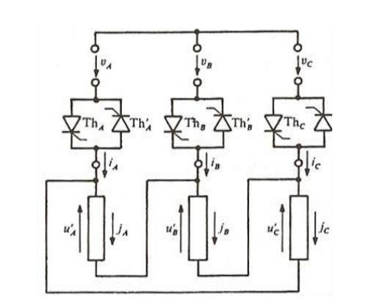
Figure (5.1) The induction motor connected to the thyristor regulator
CONCLUSIONS AND DISCUSSION
In this chapter the results of the Direct and Soft starting methods are highlighted and discussed according to the previous simulations in chapters 4 and 5.
The previous results showed that the Direct starting method requires a large starting current which causes a disturbance to voltages on the supply lines. In other words, the large starting current produces a severe voltage drop which affects the operation of other equipment. Other than that, it is a quite good method because it provides a large starting torque in a short transient state, without the need of external equipment to help starting the motor.
The previous features make the Direct starting method the most common one to start a 3ph induction motor. The Soft starting method requires a reasonable starting current to generate a small starting torque at a long transient state, not to mention the need of external thyristor voltage regulator which means extra costs. On the other hand, it provides a smooth startup without any jerks along with a controlled flawless acceleration. These features give the Soft starting method a reliable accuracy with less current needed at the expense of stationarity delay and external equipment charges.
Source: Linnaeus University
Author: Mohamad Moulham Abboud
>> Matlab Project Topics List with Free Pdf for Mechanical Students
>> Simple Matlab Projects Base Papers for Engineering Students
>> 200+ Matlab Projects for Control System for Final Year Students
>> 80+ Matlab Projects based on Power Electronics for Engineering Students