
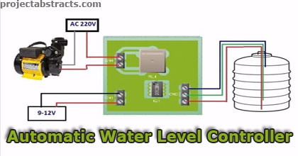
Water-level controllers are common nowadays. The one described here is built around timer NE555 and inverter buffer CMOS IC CD4049. It uses readily-available, low-cost components, and is easy to build and install on the over-head tank (OHT) to prevent wastage of water.
The circuit works off a 12V battery or 230V AC mains using a 12V adaptor. The three sensors built from non-corrosive metal are fitted to the OHT as shown in Fig. 2 and connected to the circuit (Fig. 1) at appropriate terminals.
Power supply terminal Vcc is at the bottom of the tank, sensor terminal L is just above the bottom of the tank and sensor terminal H is at the top of the tank. After you have properly installed the sensors in the OHT and connected the power supply, the circuit is ready to use.
Simple Automatic Water Level Controller
Download Simple Automatic Water Level Controller Project – 1
Download Simple Automatic Water Level Controller Project – 2
>> 100+ Easy Electronics Projects for Engineering Students
>> Electronics Mini Projects for ECE