ABSTRACT
With the rapid technological advancements of sensors, Wireless Sensor Networks (WSNs) have become the main technology for the Internet of Things (IoT). We investigated the security of WSNs in an environmental monitoring system with the goal to improve the overall security. We implemented a Secure Temperature Monitoring System (STMS), which served as our investigational environment. Our results revealed a security flaw found in the bootstrap loader (BSL) password used to protect firmware in the MSP430 MCU. We demonstrated how the BSL password could be brute forced in a matter of days. Furthermore, we illustrate how an attacker can reverse engineer firmware and obtain copies of cryptographic keys.
We contributed a solution to improve the BSL password and better protect firmware found in the MSP430 chips. The Secure BSL software we contributed allows the randomization of the BSL password. Our solution increases the brute force time to decades. The impractical brute force time improves the security of firmware and prevents future reverse engineering tactics. In addition, our Secure BSL software supports two-factor authentication that allows developers to specify a user-defined passphrase to further protect the MSP430 MCU. Our research serves as proof that any security implemented in a WSN environment is broken if an attacker has access to firmware found in sensor devices.
RELATED WORK
In this chapter, we provide related work to support different components of our thesis as well as highlight the overall history of WSNs research. We highlight various sensor applications and provide examples of related temperature monitoring systems. We discuss in detail the two security problems with WSNs that have been popular topics of research. In addition, we present various research in protecting WSNs from node capture attacks. Lastly, we end our chapter with a discussion on the not so popular topic of node tampering attacks.
- Applications
- Cipher Protocols
- Key Management Protocols
- Node Capture
- Node Tampering
SECURE TEMPERATURE MONITORING SYSTEM IN A WSN ENVIROMENT

Figure 3.2: The top image shows the front of the TelosB mote. The bottom image shows the back of the TelosB
Figure 3.2 shows the WSN topology used with our STMS consisting of a computer used to display temperature levels, a Coordinator used as a base station, a PPPSniffer used to monitor the WSN and three End-Devices used to collect temperature levels. STMS makes use of a star topology where the Coordinator serves as the central node and the three End-Devices serve as the end nodes.
The computer serves as an extension of the Coordinator to provide the user with a visual representation of the temperature data collected by each End-Device. Furthermore, the PPPSniffer node is also connected to the computer in order to provide a visual representation of the packets captured by the PPPSniffer.
The following section will provide the steps to set up STMS along with the PPPSniffer to display the capture packets using Wireshark. We assume the TinyOS IDE has been setup and the STMS code has been downloaded from our GitHub project. To avoid any path compilation errors, it is important that the downloaded STMS code is stored under the /tiny- main/apps directory. The first step of setting up the WSN environment is to plugin the TelosB motes to USB ports found on a computer. Figure 3.5 shows a USB Hub we setup to allow us to plugin all our TelosB motes to the computer that is running the Ubuntu VM.
BREAKING THE MSP430-BSL PASSWORD
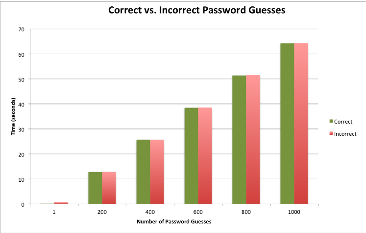
Figure 4.2: The bar graph above displays the time it takes in seconds to guess N number of correct passwords and incorrect passwords
The results show us that on average the TelosB mote is able to check 15 passwords per second regardless if the password is correct or incorrect. However, we were able to increase the passwords check significantly by changing the baud rates. The results in Figure 4.2 are an average of checking the passwords using the default BSL baud rate of 9600. Our TelosB mote supported baud rates up to 38400; therefore, significantly increasing the number of passwords checked per second. Using the same pwd-time-check.py script we added a code to change the default baud rate of 9600 to the maximum supported TelosB baud rate of 38400.
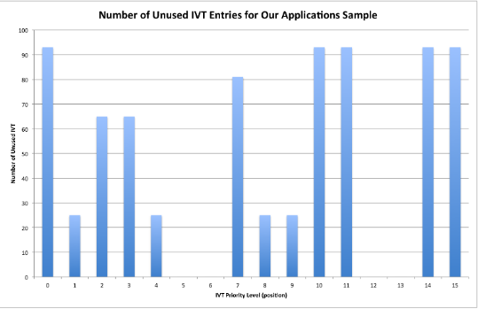
Figure 4.4: The number of unused IVT entries for our application sample size
First, sorting the addresses found in the IVT entries showed us which interrupts were most commonly unused in our applications. Figure 4.4 shows the interrupts that were unused in our applications sample. The IVT entry 15 always points to the start of the program (0x4000); thus, it will always be the same for all applications. The IVT entries 0,10,11 and 14 were never used by the applications we analyzed.
REVERSE ENGINEERING MSP430 APPLICATIONS

Figure 5.2: The process of flashing a TinyOS application to the MSP430 flash memory
Figure 5.2 shows the four- phase process of flashing a TinyOS application into MSP430 flash memory. The first phase compiles the source code (TinyOS application) using the nescc compiler and outputs a native C version of the application. The second phase compiles the native C application using the gcc compiler and outputs an ELF object file. The third phase converts the ELF object file to an IHEX object file using the msp430-objcopy command. The fourth, and final, phase flashes the binary to flash memory by reading the ASCII Text representation of the binary using the tos-bsl bootstrap loader software.
The MSP430 interconnects a 16-bit RISC Microprocessor (MPU), peripherals, and memory through the use of a memory address bus (MAB) and memory data bus (MDB). Figure 5.3 shows the functional block diagram of the MSP430-F161x MCU. The von-Neumann architecture has one address space shared with flash memory, RAM, peripherals and special function registers. Words are used to address instructions and, as mentioned in Chapter 4, words are only located at even addresses. As a Reduce Instruction Set Computer (RISC), the MSP430 only has 15 registers, 7 addressing modes and a total of 27 instructions.
PROTECTING MPS430 FIRMWARE WITH SECURE-BSL
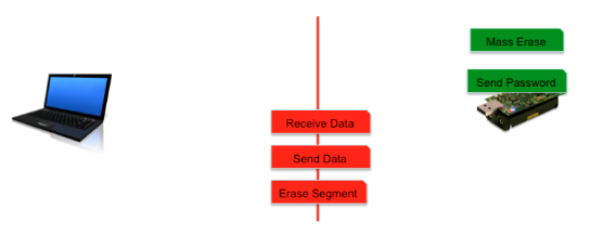
Figure 6.1: The BSL commands supported by the MSP430 without the password
The BSL code allows users or developers to communicate with the MSP430 through a USB interface. Once the TelosB mote is plugged into a USB port, a python script (tos-bsl.py) is used to communicate with the MSP430 chip. The python script uses the serial python library in order to establish and support communication between the computer and the MSP430 chip.
Furthermore, to support USB serial communication the MSP430 chip stores BSL code to respond to any commands sent by the computer. The BSL code is stored in a secure location (0x0C00-0x0FEF) that is write protected to avoid any bypass techniques if the password is unknown. Figure 6.1 shows a diagram of the BSL commands that are supported by the MSP430. The commands in green represent the commands that are allowed without the MSP430-BSL passwords.
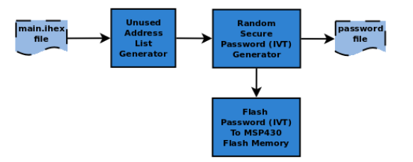
Figure 6.4: The high level components of the Secure-BSL security level one
Inside the Secure-BSL, it allows the IVT to be randomized and maintain proper functionality of the MSP430 application. The design of the Secure-BSL using security level one consists of two main components: the Unused Address List Generator and the Random Secure Password Generator. Figure 6.4 shows the process of using the main.ihex file to generate the random IVT values and output to a password file. The Unused Address List Generator component generates a list of unused addresses based on the size of the firmware to be flashed.
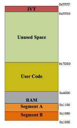
Figure 6.5: A sample of how MSP430 flash memory looks like after flashing firmware
The purpose of the Unused Address List Generator is to generate all possible addresses that can be used as new IVT values, or in other words new ISR addresses. In order to generate a list of unused address the Secure-BSL calculates the range of addresses that are not used based on the size of the binary found in the main.ihex file. For example, on average the size of a MSP430 binary is 15,840 (0x3DE0) bytes in size.
Since main memory on the MSP430 starts at address 0x4000, the average application ends at the address 0x3DE0 + 0x4000 or 0x7DE0.We know that the IVT begins at address 0xFFE0; therefore, the range of unused addresses are from 0x7DE0 to 0xFFE0. Figure 6.5 shows the memory layout of the former example. The end address is the same for all MSP430 applications; however, the start address varies depending on the size of the binary being flashed into the MSP430 flash memory.
RESULTS AND EVALUATIONS OF SECURE-BSL
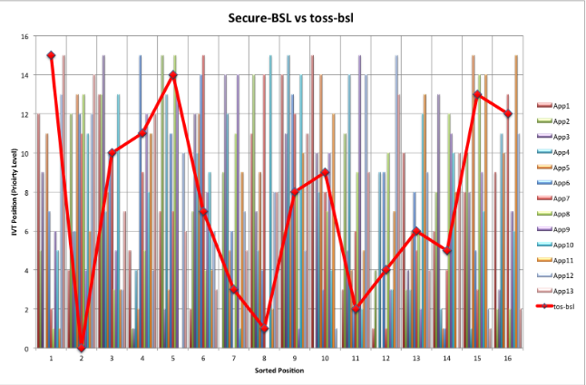
Figure 7.2: Comparing the results of the applications with 11 duplicates when using the tos-bsl vs the Secure-BSL
The bars in Figure 7.2 represent the IVT positions after sorting the interrupt handler addresses found in the secure IVT entries. The same 13 applications that were used to collect the data for the line graph were used to collect the data for the bar graphs. The data can be found in Table B.3; however, the graph presents a visual representation of the randomness found in the secure IVT entries.
For example, for the 13 applications examined, the first address of the sorted interrupt handlers corresponds to the following secure IVT positions: 12, 5, 9, 0, 11, 7, 2, 1, 6, 5, 1, 13, and 15, where the first address of the sorted ISRs for all 13 applications correspond to the original IVT entry 15. We can conclude that even if the entry address 0x4000 was always stored in IVT entry 15, our Secure-BSL software was capable of randomizing the value stored in the secure IVT entry 15 while maintaining sensor application functionality.
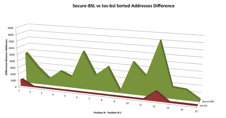
Figure 7.5: Comparison of taking the difference of the Blink application using Secure-BSL vs tos-bsl
Figure 7.5 shows a comparison of the MSP430-BSL password for the Blink application using the Secure-BSL (in green) vs the tos-bsl (in red). The tos-bsl results show that taking the difference of the sorted addresses significantly decreased the brute force time because it only required to brute force 2 of the 16 original IVT entries. Furthermore, the possible combinations for these 2 IVT entries were in the address range of 0x4000 + 900 or 0x4380 to 0x4000 + 1500 or 0x45DC. Where as the Secure-BSL results show that taking the difference of the sorted addresses did not provide patterns for potential brute force time reduction.
CONCLUSION
In this thesis we have evaluated and improved the security of WSNs by contributing a secure approach to restricting physical access to the MSP430 microcontrollers units. In Chapter 2, we discussed background information on various research topics for WSNs. We discussed various types of sensor applications and provided examples of related WSNs that remotely monitor the temperature of indoor environments. We evaluated various proposed cipher protocols for WSNs and concluded that hardware implemented ciphers are the best choice for WSNs. In addition, we mentioned various types of key management protocols and concluded that ECC is the best choice for implementing PKC in WSNs. We highlighted on different algorithms proposed to mitigate the leaking of secret information when nodes are captured. Lastly, we discussed related research of node tampering attacks and shown the possibilities of obtaining information stored the internals of MSP430.
In Chapter 3, we discussed the design, implementation and testing results of our STMS. First, we discussed our design approach of using a star topology, where the central node is a Coordinator and the end nodes are the End-Device’s collection of temperature levels. Our implementation allows to encrypt the communication between the Coordinator and the End-Devices using a network wide shared key. Furthermore, we use the AES inline encryption built in to the CC2420 RF chips of our TelosB motes. Using the PPPSniffer application and Wireshark, we were able to confirm that the communication within our STMS was encrypted. We used STMS as our WSN experimental environment to evaluate the security of the network.
Source: James Madison University
Author: Mauricio Tellez Nava
>> Top Sensor based IoT Projects for ECE/EEE Students
>> Latest IoT Projects using Microcontroller for Engineering Students
>> Latest 50+ IoT based Security Projects for Engineering Students
>> 50+ IoT based Wireless/GSM Projects for Engineering Students
>> 200+ IoT Led Projects for Final Year Students
>> IoT Software Projects for Final Year Students

