ABSTRACT
Software-based control of life-critical embedded systems has become increasingly complex, and to a large extent has come to determine the safety of the human being. For example, implantable cardiac pacemakers have over 80,000 lines of code which are responsible for maintaining the heart within safe operating limits. As firmware-related recalls accounted for over 41% of the 600,000 devices recalled in the last decade, there is a need for rigorous model-driven design tools to generate verified code from verified software models. To this effect we have developed the UPP2SF model-translation tool, which facilitates automatic conversion of verified models (in UPPAAL) to models that may be simulated and tested (in Simulink/Stateflow).
We describe the translation rules that ensure correct model conversion, applicable to a large class of models. We demonstrate how UPP2SF is used in the model-driven design of a pacemaker whose model is (a) designed and verified in UPPAAL (using timed automata), (b) automatically translated to Stateflow for simulationbased testing, and then (c) automatically generated into modular code for hardware-level integration testing of timing-related errors. In addition, we show how UPP2SF may be used for worst-case execution time estimation early in the design stage. Using UPP2SF, we demonstrate the value of integrated end-to-end modeling, verification, code-generation and testing process for complex software-controlled embedded systems.
A BRIEF OVERVIEW OF UPPAAL

Fig. 2. An UPPAAL model example.
To illustrate the above definition, consider the model from Figure 2, where both automata have separate local clocks t. Location P0:l0 has invariant t ≤10, while the edge P0:l0 ! P0:l1 has the guard condition t ≥ 10, reset action t = 0, and transmission over channel e1. Hence, synchronization over the channel e1 ensures that the transitions P0:l0 ! P0:l1 and P1:l0 ! P1:l1 occur simultaneously. Finally, note that clocks do not have to be reset to zero (e.g., as on the edge P0:l1 ! P0:l0).
EXTRACTING RUNS FROM UPPAAL MODELS
To develop the UPP2SF model translation tool, we consider the problem of extracting runs for UPPAAL models. We focus on a large class of UPPAAL models without clock conditions of the form x > E, where x is a clock and E an expression. The restriction, while not limiting in modeling of real control system, guarantees that all invariants and guards are expressed as intersections of left semi-closed (LSC) intervals. Thus, we refer to this class as Class LSC, and in this work we consider only this type of models.
BRIEF OVERVIEW OF STATEFLOW
Stateflow chart (i.e., model) employs a concept of finite state machines extended with additional features, including support for different data types and events that trigger actions in a part or the whole chart. Here, we present a small subset of the Stateflow features used in the translation procedure. Detailed descriptions of other features can be found in [sta 2012; Scaife et al. 2004; Hamon and Rushby 2007; Hamon 2005].
A state in a Stateflow chart can be active or inactive, and the activity dynamically changes based on events and conditions. States can be defined hierarchically – i.e., a state can contain other states (referred to as substates). A decomposition of a chart (or a state) determines if its states (substates) are exclusive or parallel states. Within a chart (or a state), no two exclusive states can be active at the same time, while any number of parallel states can be simultaneously activate (but executed sequentially).
UPP2SF: MODEL TRANSLATION PROCEDURE

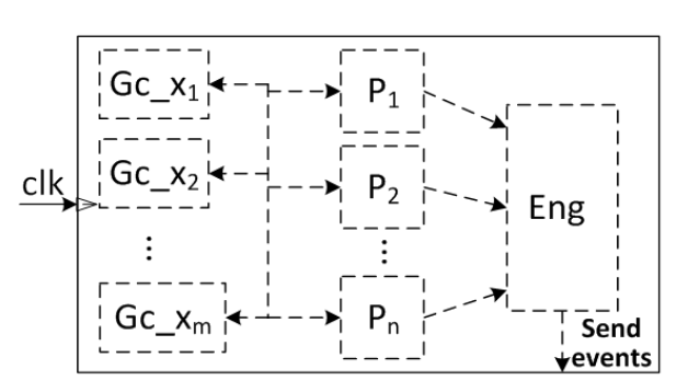
Fig. 3. Structure of Stateflow charts derived by UPP2SF.
Fig. 3. Structure of Stateflow charts derived by UPP2SF. Parent states P1; :::; Pn are derived from automata, while the clock states Gc x1; :::; Gc xm model all global clocks x1; :::; xm from the UPPAAL model. The state Eng is used to control execution of the chart.
To specify conditions over clocks, UPP2SF employs event based Stateflow temporal logic operators that (only) count the number of clk event occurrences. When the temporal logic operators are used in a chart with the two-level hierarchy shown in Figure 3, Stateflow associates a unique counter with each parallel (i.e., parent) state. It is important to highlight here that Stateflow semantics specifies that when the appropriate event activates the chart (i.e., when clk triggers the chart) all these counters are incremented at the beginning of the chart’s execution.
CORRECTNESS OF THE TRANSLATION PROCEDURE
In this section, we show that the set of rules specified in the previous section preserves the UPPAAL semantics. Specifically, we show that the execution of the obtained Stateflow chart presents one of MPA runs of the initial UPPAAL model. However, since the Stateflow semantics is informally defined, formally proving correctness of the translation procedure is not possible.
For a subset of Simulink features, there exist some attempts to derive formal semantics (e.g., [Hamon and Rushby 2007; Hamon 2005]), which have been validated by testing on many examples. We follow a similar approach in this work. We start by formulating basic assumptions on the semantics of the Stateflow charts obtained by UPP2SF – i.e., with the structure shown in Figure 3 and which utilize only a small subset of Stateflow functionalities.
IMPLANTABLE CARDIAC PACEMAKERS
![Fig. 4. (a) Pacemaker timing cycles [Jiang et al. 2012]; (b) Structure of the pacemaker model in UPPAAL, including the interaction between the pacemaker and heart, and the monitors used for verification.](http://projectabstracts.com/wp-content/uploads/2017/08/Capture285.png)
Fig. 4. (a) Pacemaker timing cycles (b) Structure of the pacemaker model in UPPAAL, including the interaction between the pacemaker and heart, and the monitors used for verification.

Fig. 5. DDD pacemaker model in UPPAAL – each automaton uses its local clock; two Random Heart templates were instantiated for Atrium (Pulse:=Ain, Art pace:=a p) and Ventricle (Pulse:=Vin, Art pace:=v p).
(Figure 5(a)) models the LRI requirement that keeps the heart rate above a minimum value by delivering atrial pace events (AP). Figure 5(b) models the AVI requirement, by mimicking the intrinsic AV delay to synchronize the atrial and ventricular events. Figure 5(c) limits the ventricular pacing rate by enforcing a lower bound on the time between consecutive ventricle events.
The PVARP automaton (Figure 5(d)) models the blocking interval after each ventricular event (VP or VS) where the atrial sensing (AS) cannot occur. The VRP automaton (Figure 5(e)) models the blocking interval for ventricular events. The interval follows ventricular events and no ventricular sensing should occur during the interval. (Figure 5(h)) model the heart as two (for both chambers) uncorrelated random pulse generators with a single constraint that in each chamber the times between two consecutive events are within the predefined interval.
PACEMAKER STATEFLOW DESIGN

Fig. 6. Pacemaker Stateflow chart extracted using UPP2SF from the UPPAAL model in Figure 5; the heart and buffer models are highlighted.
Note that the verified UPPAAL model also contains several monitors used to specify verification queries. Since none of these monitors uses shared variables, and they only interact with the rest of the model by receiving synchronization over broadcast channels, they do not affect behavior of the basic automata from Figure 5. Thus, to simplify Figure 6, we did not show the parallel states that were obtained from them.
PACEMAKER IMPLEMENTATION

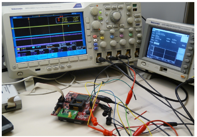
Fig. 8. Hardware setup with MSP430F5438 experimenters board.
The pacemaker code generated by the Simulink RTWEC was executed on nanoRK [nan 2013], a fixed-priority preemptive RTOS that runs on a variety of resource constrained platforms. We tested the implementation on the TI MSP-EXP430F5438 Experimenter Board interfaced with a signal generator that provides inputs for the pacemaker code (Figure 8).

Fig. 9. Transition monitors (TrMonitor) used for the worst-case execution time estimation.
The reason for this is that the transition monitor from Figure 9(a) does not take into consideration the order of the input events processing, and if both AinB! and V inB! occur at the same time instance, the UPPAAL model might synchronize over the channel AinB first. On the other hand, the pacemaker model in Stateflow, and thus the obtained code, have a fixed input ordering, meaning that the inputs are always processed in the predefined order; in the pacemaker code V inB is always processed before AinB (and the clk event is processed last).
CONCLUSION
We have described the design of the UPP2SF tool for automatic translation of UPPAAL models in Stateflow. We have shown that for a large class of UPPAAL models, UPP2SF preserves behavior of the initial UPPAAL model. Furthermore, we have presented an UPP2SF-enabled Model-Driven Development framework for safety-critical system design.
By applying the UPP2SF model translation tool on the dual-chamber, implantable cardiac pacemaker case study, we have demonstrated the process starting from the formalization of the device specifications, followed by system modeling and verification in UPPAAL, to closed-loop system simulation in Simulink/Stateflow and testing of the physical implementation.
We have also shown how the translation tool provides a way to estimate WCET during modeling and verification stage in UPPAAL, and facilitates development of modular code from UPPAAL timed-automata based models. The presented case-study fits into the scenarios where the system is controlled using a single, centralized, controller. We plan to investigate the use of the UPP2SF-based MDD framework for code synthesis for distributed applications.
Source: University of Pennsylvania
Authors: Miroslav Pajic | Zhihao Jiang | Insup Lee | Oleg Sokolsky | Rahul Mangharam