ABSTRACT
This paper examines a co-design of control and platform in the presence of dropped signals. In a cyber-physical system, due to increasing complexities such as the simultaneous control of several applications, limited resources, and complex platform architectures, some of the signals transmitted may often be dropped. In this paper, we address the challenges that arise both from the control design and the platform design point of view.
A dynamic model is proposed that accommodates these drops, and a suitable switching control design is proposed. A Multiple Lyapunov function based approach is used to guarantee the stability of the system with the switching controller. We then present a method for optimizing the amount of platform resource required to ensure stability of the control systems via a buffer control mechanism that exploits the ability to drop signals of the control system and an associated analysis of the drop bound. The results are demonstrated using a case study of a co-designed lane keeping control system in the presence of dropped signals.
DEFINITIONS
We define Lyapunov Like Functions (LLF), switching systems, and related stability properties, which are used throughout this paper. The system of interest in this study is a switching system with n modes
x [k+1] = fi (x[k]); i = 1; 2; … , n
We denote the jth instant at which the system switches to mode i as tji .
STATEMENT OF THE PROBLEM
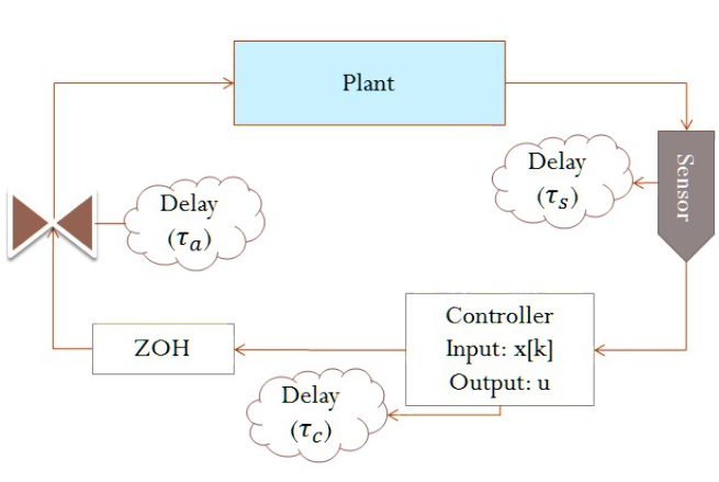
Figure 1: Schematic overview of the control of a plant using a DES.
We assume that the plant is periodically sampled with a fixed period T, and define t = τa +τs +τc (Fig. 1), where τs, τc, and τa are the processing times for the sensor task, the control computation, and the computed output to be communicated to the actuator. We define τth as a threshold value for τ and assume that τth < T. If the delay τ exceeds τth, we assume that the control computation may arrive too late for it to be effective in controlling the plant.
STABILITY OF THE SWITCHED SYSTEM WITH A MAXIMUM OF M0 DROPS
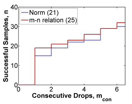
Figure 2: Comparing the methods of Example 1.
The results in Fig. 2 are with assumption that the packet dropouts in in any interval m+n+1 consist of only up to m messages that occur consecutively. It can be seen that provides a lower bound for n without the need for iterative computation of the norms.

Figure 3: Relation between sequence ki.
We start with k = ki, and assume without loss of generality that j1 drops occur starting at ki +1 (see Fig. 3). System consists of two modes, the dropped mode, and the stable mode, with the dropped mode occurs from ki to ki + j1 +1 and the stable mode from ki+ j1+1 to ki+i1 + j1 +1. Defining
k2i = k2i-1+ j1+1 and k2i+1 = k2i +N; i = 1;2; …
STABILITY CONDITIONS WITH M DROPS USING A MULTIPLE LYAPUNOV FUNCTION APPROACH
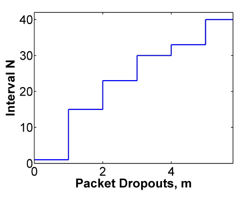
Figure 5: Number of allowed dropped samples in interval N.
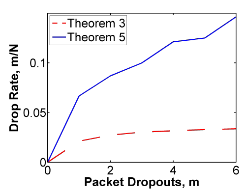
Figure 6: Comparison of Theorem 5 versus Theorem 3.
We consider the discrete time system of example 1. Figure 5 shows the maximum number of drops in the window of size N using the results of Theorem 5. Figure 6 compares the results of Theorem 5 with those of Theorem 3, illustrating that the former are much less restrictive compared to the matrix inequalities in Lemma 2. We note that the difference between the results of Theorem 3 presented in Fig. 6 and those presented in Fig. 2 come from the possibility that m drops can occur at any time over an interval N.
LANE KEEPING SYSTEM
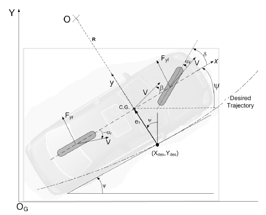
Figure 7: Vehicle model.
The control task is to keep a vehicle in its lane with radius R (Fig. 7). A one track model of a Ford Taurus was used for this purpose. Dynamics of the vehicle can be described.
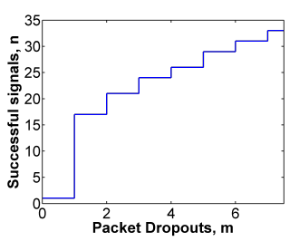
Figure 8: n versus m in the lane keeping system.
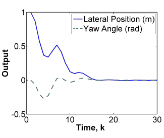
Figure 9: Response of the vehicle with m = 1 and N = 6.
The variations in m with n are plotted in Fig. 8. These results show that as n and therefore N increases, m changes. This information directly provides guidance to the platform designer as it indicates the allowable number of drops over a given time interval. Figure 9 shows resulting closed-loop system performance of e1 and e2 for the case of N = 6 and m = 1, which illustrates a satisfactory quality of control performance.
OPTIMIZING RESOURCE VIA PLATFORM CONTROL

Figure 10: A platform architecture for a control system.
We assume that the system has been partitioned into a set of tasks that are mapped onto different processing elements (PEs) of a fixed platform architecture (c.f. Fig. 10), which is given a priori. Our goal is to minimize the amount of resource (expressed in terms of processor frequency or communication bandwidth) that the PEs must provide to ensure the control stability.

Figure 11: Buffer control mechanism for the platform.
Observe that partially processed samples at intermediate PEs may already become stale, i.e., their delays exceed the threshold τth. Therefore, it is safe to drop these samples at the intermediate PEs instead of continuing processing them until they are fully processed. The buffer control mechanism works during run-time at each buffer in the system (see Fig. 11) as follows.

Figure 12: The transformed system that is used for the analysis.
From the above observation, we can compute the drop bound by analyzing the transformed system shown in Fig. 12. Since the shaper does not drop any samples, we only need to consider the parts of the system before the shaper. Without loss of generality, we assume βu is sub-additive and βl is super-additive.3 We first verify a special case in which no samples are dropped, i.e., m = 0.
CASE STUDY
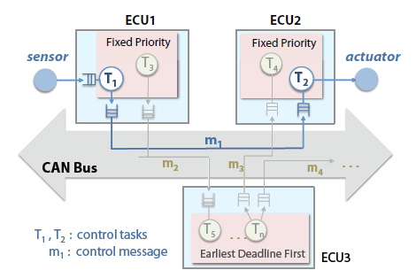
Figure 14: System architecture for the lane keeping system.
Fig. 14 shows a lane keeping system that is mapped onto a CAN architecture. Each sensor value that arrives from the sensor cluster is first processed by the control task T1 on ECU1. The processed slip value is then sent to ECU2 via the message m1. Upon arriving at ECU2, the slip value is used by T2 to compute the steering angle, which is required by the wheel brake actuator for the wheel steering thus keeping the vehicle in lane.
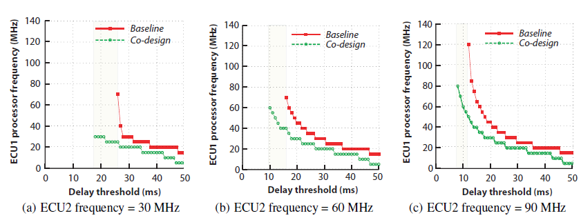
Figure 15: ECU1 processor frequency for different delay thresholds.
Fig. 15 shows the minimum frequency of ECU1 computed using the two methods for three different frequencies of ECU2 (30MHz, 60MHz, and 90MHz) and a medium-speed CAN bus (250 kBits/s). We observe that the co-design method consistently outperforms the baseline method.

Figure 16: ECU1 design feasibility regions with respect to different bus speed values.
We also observe from Fig. 16 that the feasible region of the baseline method consistently falls strictly inside that of the co-design method. Further, when ECU2 operates at 10 MHz, no solution exists for the baseline method, regardless of the threshold delay and bus speed values. Thus, our co-design method not only enables resource savings but also provides more flexibility for the platform design.
CONCLUSION
We have presented a control and platform co-design method for cyber-physical systems, which allows dropped samples to optimize resource while guaranteeing the control quality. We have developed a dynamic model including delay and analyzed its stability switching theory criteria. First using matrix inequalities, an upper bound for the maximum number of packet dropouts in any interval was derived to guarantee stability. Then a more practical approach using a multiple Lyapunov functions was developed and proved. The latter allowed more freedom in the platform design.
A buffer control mechanism was introduced that utilizes the control design capability in accommodating dropped samples to reduce the resource requirements of the system. We have also presented a technique for computing the drop bounds under the proposed mechanism, and demonstrated how they can be used for dimensioning the platform resource. Our evaluation results of a lane keeping control system case study shows that our co-design method not only helps improves the resource use efficiency by an order of magnitude but also enables design solutions that are infeasible under the conventional baseline design approach.
Source: University of Pennsylvania
Authors: Damoon Soudbakhsh | Linh T.X. Phan | Oleg Sokolsky | Insup Lee | Anuradha Annaswamy