ABSTRACT
This paper includes design and implementation result of an adaptive beam forming antenna for upcoming 5G and Internet of Things (IoT). Switched parasitic array antennas are low cost, small sized and compact circular array antennas that steer beam in a desired direction by variation in switching pattern of parasitic elements.
The proposed antenna design has an active center element, which is surrounded by several symmetrically placed parasitic elements. The designed antenna has a gain of 8dB and is capable of 360 degrees beam steering in steps of 60 degrees each. Simulations are validated with results of the fabricated antenna. Antenna beam is steered by controlling parasitic elements. Future application of Electronically Steerable Parasitic Array Radiator (ESPAR) antennas and switched parasitic array antennas in next generation communication networks and methods for reducing size of the antenna are also highlighted.
SWITCHED PARASITIC ARRAY ANTENNA CONCEPT
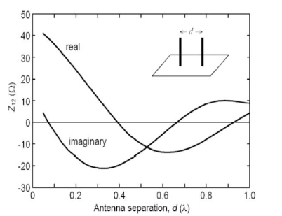
Fig. 2. Z21 versus separation distance
Here Z22 is constant as it is open-circuit output impedance. Z21 is open-circuit transfer impedenace from port 2 to port 1 and it can be approximated by graph shown in Fig.2.
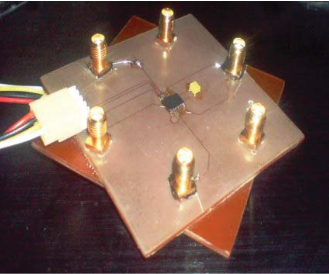
Fig.3. RF PCB with Analog devices ADG 904 RF switches
In this work the designed antenna is capable of 3600 beam steering in steps of 600. The beam steering is achieved by using two sets of 4:1 Analog devices multiplier switch ADG 904. Fig.3 shows RF PCB designed for beam steering. Beam is steered towards an element which is open. The open element behaves as a director and shorted elements act as reflectors. In order to achieve a maxima at 00, we make the element 1 open by using RF switch IC while other elements (i.e., elements 2,3,4,5 and 6) are shorted.
PARASITIC ARRAY ANTENNA DESIGN
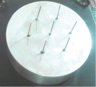
Fig.4. Designed seven element parasitic switched array antenna
Monopole elements are made by cutting copper wire of desired gauge i.e lambda/200 in radius and these elements are soldered on pin of SMA connectors. Aluminum is used as ground plane. Electromagnetic waves are reflected by the ground. Instead of using seven dipole elements we have used seven monopole elements mounted on the ground plane. Ground is made hollow in order to create space for mounting control circuitry. Fig.4 shows designed hardware.
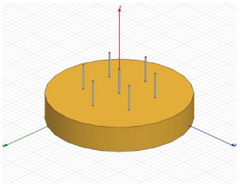
Fig.5. Simulated antenna model
The antenna is first simulated and then simulated results are compared with the measured results of fabricated antenna. Simulated results were in line with the hardware results and 8dB gain was observed in simulated results as well as in fabricated antenna. In simulation each of the parasitic element is loaded with lumped port excitation, simulating opening and shorting of monopole elements. Fig.5 shows simulated model.
ANTENNA SIMULATION AND PLOTS
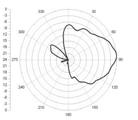
Fig.6. Anechoic chamber results for θ = 900 (Beam in elevated because we are using monopole elements with finite ground)
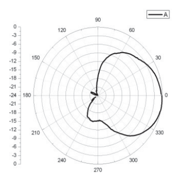
Fig.7. Anechoic chamber results for φ = 00
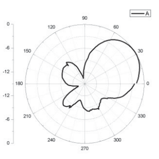
Fig.8. Anechoic chamber results for φ = 300
Two dimension polar plots depicts the beam steering in the direction of given elevation angle, theta (θ) and azimuth angle, phi (φ). Anechoic chamber results for θ =90 and φ =0 and 30 degrees are shown in Fig.7 and 8 respectively. Using large ground plane angle of elevation is reduced closer to 900. Fig.6 shows anechoic chamber result for θ =90 one can observe small elevation form desired x-y axis because of ground skirt.In simulations elevation angle of 850 is observed.
Fig.6(a) shows antenna simulated plot for elevation angle θ and Fig.6(b) shows anechoic chamber results.Anechoic chamber plot of Fig.7 shows maxima at φ = 00, in order to get maxima at 00 elements from element number 2-6 are shorted and the element 1 is opened. Similarly Anechoic chamber plot of Fig.8 shows maxima at φ = 300, in order to get maxima at 300 elements from element number 3-6 are shorted and element 1 and element 2 are open.
CONCLUSION
5G networks will be designed for device to device, device to human and human to human interactions. High data rates are required to meet demands of 5G systems. One of proposed bands for 5G is in mm-Waves range i.e from 30GHz to 60GHz for such high frequencies path losses are considerable and beam steering antennas are way forward to overcome path losses. ESPAR and switched parasitic array antennas provide a cost effective way of incorporating adaptive beam- forming in future 5G and internet of Things (IoT) devices. However for the efficient use of ESPAR antennas in mobile terminals the size of the antenna system must be reduced, for this further research on dielectric switched parasitic array antennas is underway.
Seven element switched parasitic array antenna is designed that is capable of dynamic beam steering. Gain of 8dB is achieved practically. Simulated results are in line with the anechoic chamber results. Designed antenna increase the channel capacity by improving signal to noise ratio. Gain of 8dB was achieved in specified directions of elevation angle,theta (θ) and azimuth angle, phi (φ). Antenna is optimized in terms of interference reduction for its use in wireless adhoc networks, operating at frequency of 2.45 GHz. Bandwidth of designed antenna is 450 MHz and beam is steered in 3600.
Source: Boise State University
Authors: Ahmed Kausar | Hani Mehrpouyan | Mathini Sellathurai | Rongrong Qian | Shafaq Kausar
>> 50+ IoT based Wireless/GSM Projects for Engineering Students
>> 60+ Antenna Communication Projects for Engineering Students
>> Smart Antenna Design Final Year Projects for Engineering Students
>> More Wireless Energy Projects for Engineering Students