ABSTRACT:
The Autonomous Golf Cart Project is a project sponsored by the Cal Poly Robotics Club. The multidisciplinary team is adding sensors and electronics to a regular golf cart with the goal to drive the golf cart around campus without and human input.
This task requires a plethora of hardware and firmware to control that hardware. The firmware provides an interface for higher level software to then control the hardware and therefore drive the golf cart. This report is focused on the hardware modifications and the firmware used in order to drive the golf cart from a computer.
GOLF CART HARDWARE:
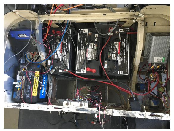
The golf cart has been retrofitted with electronics to enable the entire system to be controlled from a computer. The golf cart uses a 2 Horsepower electric motor connected to the rear axle in order to drive. This motor is powered off three 12 V batteries in series to create an effective 36 V power source. This supply is connected through a power solenoid, to a speed controller, and then to an H-Bridge.
The power solenoid is a safety feature to ensure that the motor only receives power when someone is on the golf cart. The power solenoid is activated by arming an emergency stop switch, and by slightly depressing the pedal. When both these events have occurred, the solenoid connects and allows current to flow into the H-Bridge and speed controller.
GOLF CART SENSORS:
The golf cart uses multiple sensors to gain information about its surroundings. First and foremost is the LIDAR, which is similar to a radar, but uses light instead of sound waves. By bouncing light pulses off of surfaces and recording the time-of-flight for each pulse, the distance to the surface can be measured with a high degree of accuracy.
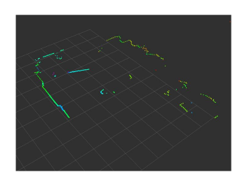
The LIDAR used on the golf cart scans 270° with 0.5° resolution at 30 Hz. This is known as a 2D LIDAR as it scans its surroundings on a 2D plane. Sample LIDAR data, along with a picture of the scene.
CONTROL BOARD:
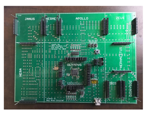
The control board is not a single PCB, but a collection of smaller PCBs. All these smaller boards, or daughter cards, connect to single mother board known as Olympus. This approach allowed the controls boards to be developed in parallel. It also simplifies each board, reducing the chance for mistakes. Also if a single board breaks, only that board needs to be fixed. The next sections detail each of these control boards. An images of the control board with and without the daughters are shown in figures 5.
FIRMWARE:
Much of the firmware involves reading and writing the MCU’s peripherals. The firmware for the control board is built to reduce the opportunity for race conditions. This is done through the use of service functions called from a main loop. While Interrupt Service Routines (ISRs) are used throughout the code, work actually done in their routines is minimal. This work is limited to copying data out of a peripheral and setting a flag to indicate the further processing needs to be done. In the main loop, these flags are constantly checked inside service functions to in order to process the peripheral.
FIRMWARE DRIVERS:
It is not enough to just read from the sensors. In many cases it is necessary to react to sensor readings directly in the firmware.
Steering Driver:
n order the steer the golf cart, the firmware must read from the steering potentiometer to detect the current angle of the steering wheels, and then write to the steering H-Bridge on the Janus board in order to actually steer the front wheels left or right. The steering driver makes use a callback timer, and is currently called every 100 milliseconds, or at 10 Hz, although not much work has been done to find the optimal value.
USB Communication Interface:
The native USB interface is designed to handle the bulk of the communication between the Linux computer and the control board. It is designed around command and response packets, where a command could be “Set FNR” or “Get Power levels”. A command packet may contain data if necessary. Once the control board receives a packet, it processes the packet and sends a response back to the Linux computer.
FUTURE IMPROVEMENTS:
As the firmware has been implemented, many new features and fixes to the current firmware have been suggested. As of now these fixes have not been implemented, but they are planned for the next couple of months.
It is yet to be seen how the switch to many service functions inside the main loop will affect performance. It has already drastically reduced the amount of debugging time needed to check for race conditions, but that comes at the cost of efficiency. In the coming months it will be necessary to profile the firmware in order to see if the service model has negative affect on the total efficiency of the firmware.
Often when the command line is being used the same command is issued over and over again in order to check the hardware. Currently there is no way to repeat the last command entered like one would expect in a Linux command line. Added a history, even if small, would increase productivity when using the command line to debug.
CONCLUSION:
With the current version of the firmware, all electronics necessary to drive and steer the golf cart are operational. This has allowed the team to perform milestone 1, where the golf cart is driven at a wall and stops to avoid hitting it.
The detection of the wall is done using the LIDAR. As the golf cart approaches the wall, the Linux computer will send commands to lower the current speed. Once the golf cart is too close to the wall, the computer will switch the golf cart to reverse and back away from thewall at a fixed speed.
This test control most of the golf carts electronics, with the exception of steering. A second test was performed where cone was placed in from of the golf cart. As the golf cart approached the cone it continuously checked to see if it could turn to avoid the cone. If it could, it would then turn to avoid the object. Otherwise it would stop. This tested all the electronics needed to drive the golf cart.
The next step is to create a test that integrates all the golf cart sensors, including the ultrasonicand hall effect sensors. This test is still in development and the team is excited to finally integrate all the golf carts sensors into a single test.
While there is still some work to be done on the firmware. I am satisfied with the current state of the firmware and believe that the remain team members will be able to finish up the last firmware tasks. I am also excited to see where the team is able to take the project in the future.
Source: Cal Poly
Authors: Gerik Kubiak


