ABSTRACT
A system for automatic mounting of high tolerance wedges inside a wave power linear generator is proposed. As for any renewable energy concept utilising numerous smaller generation units, minimising the production cost per unit is vital for commercialization. The linear generator in question uses self-locking wedges, which are challenging to mount using industrial robots due to the high tolerances used, and because of the fact that any angular error remaining after calibration risks damaging the equipment.
Using two types of probes, mechanical touch probes and inductive proximity sensors, combined with a flexible robot tool and iterative calibration routines, an automatic mounting system that overcomes the challenges of high tolerance wedge mounting is presented. The system is experimentally verified to work at mounting speeds of up to 50 mm s−1, and calibration accuracies of 0.25 mm and 0.1◦ are achieved. The use of a flexible robot tool, able to move freely in one Cartesian plane, was found to be essential for making the system work.
METHOD

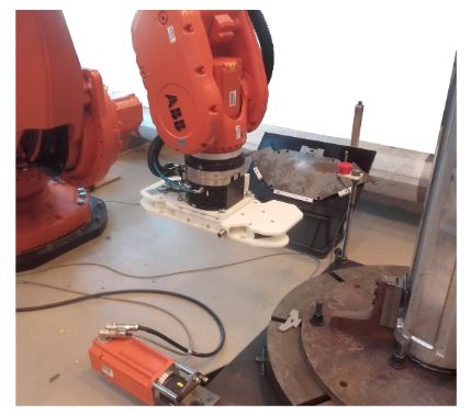
Figure 2. Photo showing the ABB6650s robot (upper left), the rotational table (lower right)

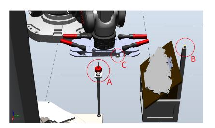
Figure 3. CAD model of the robot cell, showing the placement of the three main sensors used during measurement
The robot used for these experiments was a floor mounted ABB6650S, shown in Figure 2. Next to the robot is a rotational table, carrying the central pipe of the translator. The secondary smaller table is used as storage for the pole-shoes. Mounted on the end of the robotic arm is a robot tool, designed to lift and manipulate the pole-shoes.
Three main sensors were mounted in the cell, one touch probe and two inductive proximity sensors, shown in Figure 3. The touch probe (Sensor A) and one inductive proximity sensor (Sensor B) was mounted in proximity to the pole-shoe storage and were used to measure the orientation and translation of the pole-shoes, once lifted by the robot tool.
RESULTS AND DISCUSSION

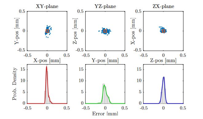
Figure 8. Planar position point-clouds (top) and deviation distribution (bottom) for 200 measurements of the pole-shoe TCP using a touch probe (Sensor A)
The results from the measurements of the robot tool’s TCP using the touch probe (Sensor A) is shown in Figure 8, where the center point is defined as the average of all measurements. The standard mean deviation, σ in the x-, y- and z-positions was calculated to be 0.029 mm, 0.051 mm and 0.032 mm, respectively.

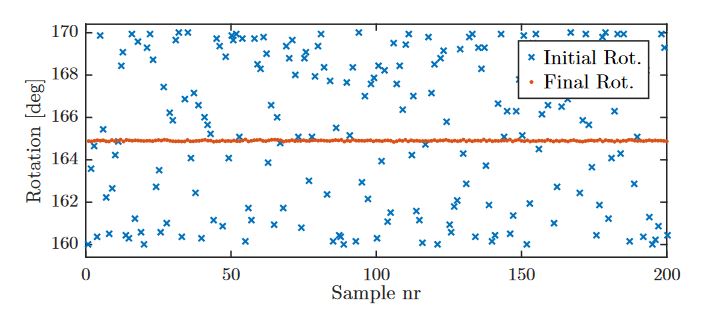
Figure 12. Initial and final rotation of the pipe for 200 calibration cycles for the 165◦ case
The average final position, as reported by the robot’s internal axis tracking, for each side was 44.90◦, 164.90◦ and 284.90◦, respectively, giving an average absolute error of 0.1◦, if compared to the theoretically optimal values of 45.0◦, 165.0◦ and 285.0◦, with an average σ of 0.025◦. Figure 12 shows the initial and final rotation for each sample for the 165.0◦ case, and the other two cases showed similar results.
FUTURE WORK
The method presented in this paper is to be seen as a proof of concept, leaving room for future improvements. While the presented solution has shown that it is possible to mount a few pole-shoes without error, it has not addressed the question of how to repeat it continuously. This is something that needs so be investigated before an implementation in a real production line is attempted. In addition, some kind of safety and backup systems, in the unlikely event that the pole-shoe locks up despite being calibrated, remains to be developed and will be necessary to have in a full-scale system.
CONCLUSIONS
A method for mounting high tolerance wedges, for use in a linear wave power generator, using an industrial robot have been developed and experimentally verified. Two types of sensors were evaluated for calibrating the workpiece, where the touch probe was proven superior to the inductive proximity sensor. The combined accuracy of the pole-shoe and pipe calibration was, however, not accurate enough to allow for the use of a fixed robot tool during the mounting action.
Using a spring loaded tool, which allowed movement in the xy-plane, was therefore necessary in order to perform a fully automatic mounting action in the z-direction. Future work needs to be done on increasing the speed of the pole-shoe calibration, now accounting for 87 % of the calculated assembly time.
Source: Uppsala University
Authors: Tobias Kamf | Mats Leijon