ABSTRACT
Agricultural researchers are constantly attempting to generate crops superior to those currently in use by the world. Whether this means creating crops with greater yield, crops that are more resilient to disease, or crops that can tolerate harsh environments with fewer failures, test plots of these experimental crops must be studied in real-world environments with minimal invasion to determine how they will perform in full-scale agricultural settings.
To monitor these crops without interfering on their natural growth, a noninvasive sensor system has been implemented. This system, instituted by the College of Agricultural Sciences and Natural Resources at the University of Nebraska – Lincoln, uses a network of cables to support and maneuver a sensor platform above the crops at an outdoor phenotyping site.
In this work, a cable-driven parallel robot (CDPR) to be used by the university’s agricultural researchers is modeled for static behavior. This model is then compared to scaled-down CDPRs to confirm its accuracy. Second, the scaled-down CDPRs are used to study the dynamics of cable systems, test scaled-down end-effectors, and develop a CDPR control scheme.
Third, a novel stabilization system is developed to maintain sensor platform orientation, improving data collection by use of a multirotor stabilization system. Multiple prototype systems are developed and experimented with to determine the capabilities and limitations of such a system. Finally, a portable CDPR system for use in remote fields is analyzed for cost feasibility and design considerations.
CABLE-DRIVEN ROBOT STATIC ANALYSIS
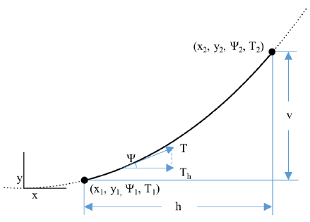
Figure 2-1. Sagging cable catenary parameters.
In flexible cables with significant, evenly distributed mass, the weight of the cable provides varying vertical load along the length of the cable, which generates a curve as defined by (2-1) and is illustrated in Figure 2-1.
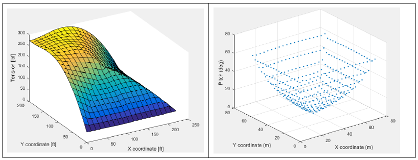
Figure 2-3. Model mesh outputs. (left) Theoretical cable tension. (right) Theoretical end-effector pitch.
Based on this assumption, cable tensions are solved across one quadrant of the workspace, and the behavior of the system in all other quadrants is then extrapolated based on the symmetry of the workspace. Figure 2-3 displays tension for a single cable as a function of end-effector position in the field at a fixed height. 2 Figure 2-3 also illustrates the amount that the end-effector is predicted to tilt as a function of end-effector position in the field at a fixed height.
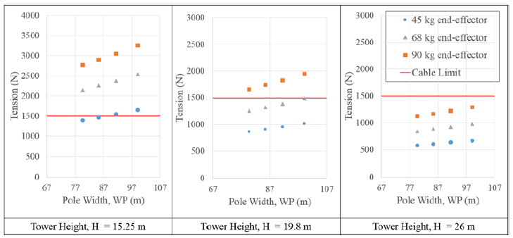
Figure 2-5. Theoretical maximum tension in field.
Many simulations were generated with different permutations of tower height, tower distancing, and end-effector mass. Selected results from these simulations are presented in Figure 2-5. Figure 2-5 shows the influence of all three variables on the predicted maximum tensions for the system within the operational workspace.
CABLE-DRIVEN ROBOT CONTROL THEORY
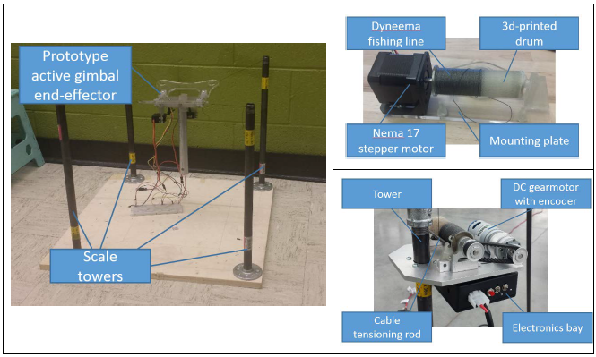
Figure 3-1. CDPR model components. (left) Desktop prototype. (right-top) Initial winch design using stepper motor. (right-bottom) Current CPDR winch, using DC gearmotor and encoder.
The winches went through several iterations. In the desktop model and the first 12th scale system, stepper motors were used to actuate 3d-printed drums (Figure 3-1). By the final design see Appendix F for design files the motors were replaced with DC brushed motors with encoders to remove cable-feed tracking errors caused by misstepping in the original motors.
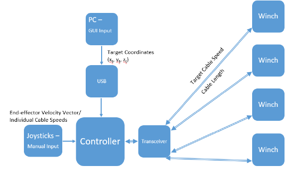
Figure 3-3. CDPR control scheme.
The basic CDPR control scheme is illustrated in Figure 3-3 and operates as follows. The controller receives an input from one of two sources: it receives a destination in the workspace to move the end-effector to from a PC connected to the Arduino’s USB port, or it receives a desired velocity vector for the end-effector from the two on-board joysticks.
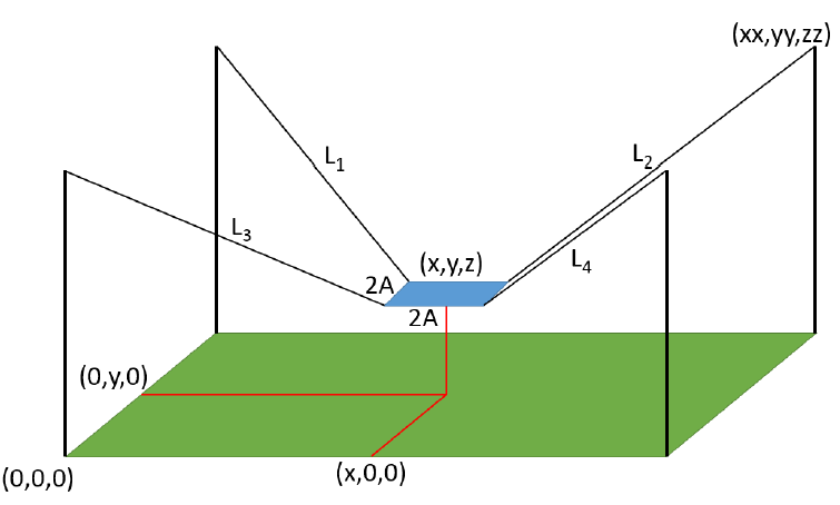
Figure 3-4. Control system dimensional layout.
In Manual Winch Control mode, the two joysticks are used to individually control the four cable actuation winches. The x and y-axis (or horizontal and vertical) signals from the left joystick correlate to the line-speed of cables one and two, respectively, while the x and y-axis signals form the right joystick correlate to the line-speed of cables three and four (Figure 3-4).
SCALED SYSTEM DESIGN AND EXPERIMENTATION
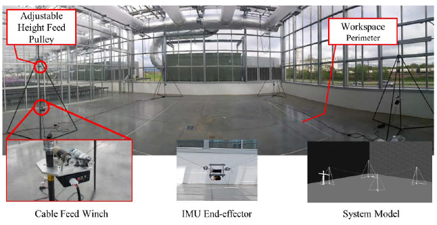
Figure 4-1. One-twelfth-scale system.
A one-twelfth-scale model of the field phenotyping system, shown in Figure 4-1, was designed to confirm the simulator results presented in Chapter 2 and to test control system designs from Chapter 3 as well as system dynamics, and end-effector stabilization hardware and controls.
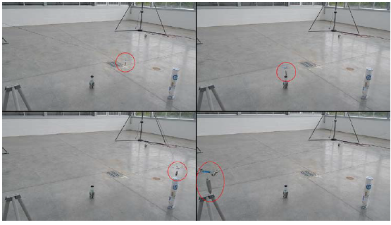
Figure 4-5. CDPR positioning experiment.
To test the capabilities of the navigation system, a network of obstacles to maneuver were setup within the CDPR workspace. Using both manual/joystick input and automated/ GUI input, a dummy end-effector with a suspended plumb bob was maneuvered around the field, moving around obstacles and positioning the tip of the plumb bob directly above each obstacle, as in Figure 4-5.
AEROMOTIVE STABILIZATION OF A SUSPENDED PAYLOAD
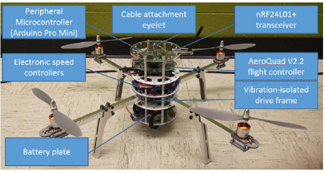
Figure 5-1. AeroQuad-based IPASS prototype. Tethers not shown.
For proof of concept, a quadcopter was suspended from the one-twelfth-scale system, and the quadcopter’s response to disturbances was recorded. In addition, conceptual tests were performed to determine the feasibility of multiple control concepts discussed below. A prototype end-effector was constructed from a modified, Arduino-based quadcopter, shown in Figure 5-1, utilizing a standard quadcopter PID control based on accelerometer and gyroscope feedback.
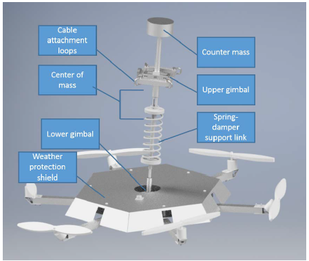
Figure 5-4. Full-scale end-effector model.
The primary influence on settling time seen in the proof-of-concept experiments was the positioning of the end-effector center-of-mass. In the previous experiments, the mass was located so far below the support point of the end-effector that a large rotational inertia had to be overcome to stabilize the end-effector. To reduce system inertia and achieve a faster response, the center-of-mass should be located at or just below the end-effector support point, as illustrated by Figure 5-4.
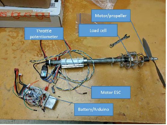
Figure 5-7. Propeller thrust measurement apparatus.
In addition to this analytical solution, an equation was derived experimentally to determine throttle as a function of desired thrust. This experiment consisted of mounting a single motor and propeller to one end of a load cell while the other end was mounted to a long shaft, allowing to the apparatus to be held away from the user and surrounding obstructions to airflow. The device is shown in Figure 5-7.
MOBILE PHENOTYPING SYSTEM
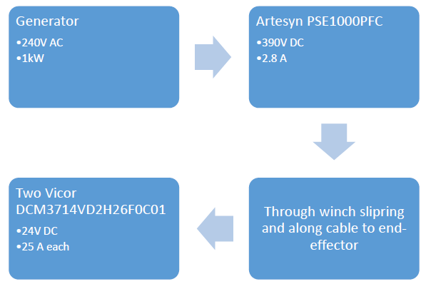
Figure 6-6. End-effector power flow.
To maintain an autonomous system with reduced oversight, the power can be generated at one of the trailers, scaled to a higher voltage, transmitted along one of the support cables, have the voltage be dropped down to a usable level on the end-effector, and then be grounded through a second cable. Running a quick search through Digikey’s website, preliminary hardware has been found to perform this task, as illustrated by Figure 6-6.
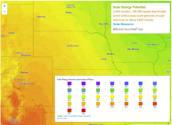
Figure 6-13. Solar Energy Potential Map.
A solar power system’s ability to power this system is largely dependent on the availability of solar energy in the target area. Based on the resources made available by the US Department of Energy and illustrated in Figure 6-13, the majority of Nebraska can expect an annual average of 440-520 Watt-hours per square foot per day.
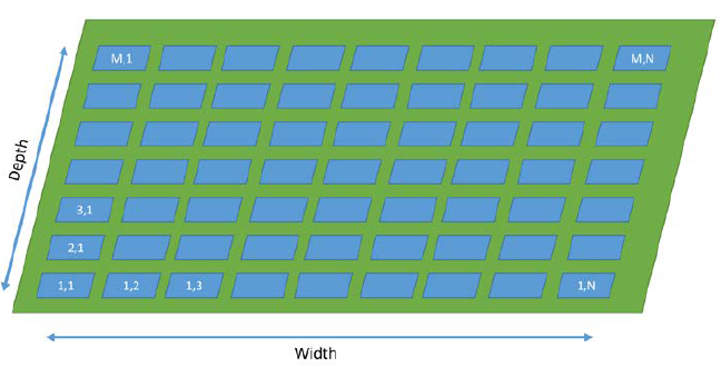
Figure 6-7. Mobile system plot layout.
During the scanning process, there are two modes that the system will behave in. One when it is traveling and the winches are drawing power and the other when it is scanning and the sensors and stabilization system are drawing power. To solve the amount of power required to navigate the end-effector through its flight path for one scan, a field such as in Figure 6-7 is imagined.
CONCLUSIONS
The first aspect of this feasibility analysis is the cost estimate, as laid out by Table 6-4. As it shows, the bulk of the cost is the towers and winches. However, these costs are for only four units of each for prototyping. Should this system become commercial, procurement costs for these parts should be expected to lower as a large portion of the cost should currently be going towards engineering and not materials or manufacturing.
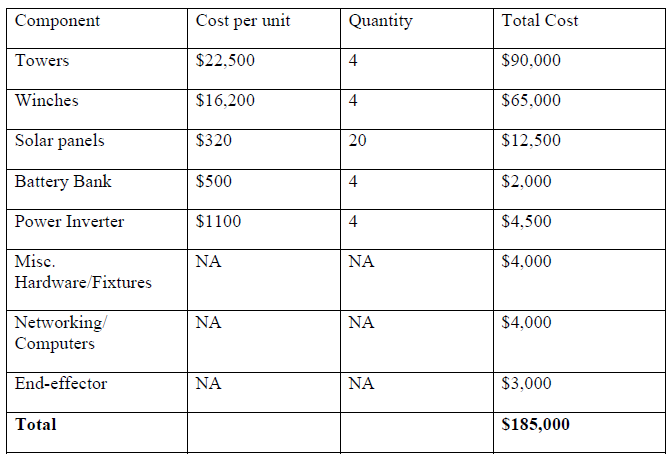
Table 6-4. Mobile system cost estimation.
The next largest cost is the solar power system. While the system would likely cost greater than $20,000 when everything is finished, the long-term savings could make it a viable power system. Overall, the estimated cost for a prototype system is $185,000. Provided that the current investment into the permanent system at Mead is in the realm of one million dollars, it is the opinion of this analysis that this system is fiscally feasible.
From an engineering perspective, no challenges have been found to declare this system infeasible; however, there are certain concerns that will require further analysis should design progress. First, power generation and distribution will present challenges. While a single generator presents the most simplistic and possibly cheapest option, it presents issues by requiring large cables to pass around the field, potentially impeding farming operations. Local generators and solar panels have their issues as well, as previously discussed, but the largest engineering challenge in the area of power management is the task of supplying the end-effector with power.
Source: University of Nebraska
Authors: Matthew Newman