INTRODUCTION
Erin James, a caramel candy proprietor and sponsor of this project has requested the design and build of a machine that will allow her to reduce the amount of time spent cutting and wrapping homemade caramels as this process currently takes too long to be commercially competitive. As a small batch confectioner who uses her home kitchen, Erin requires a machine that is low cost, compact enough to store and operate in her house, and capable of wrapping one batch, or 144 caramels, in approximately 10 minutes. This would reduce the amount of time it takes to complete this process by 35 minutes from the current time of 45 minutes that it takes her to cut and wrap the caramel by hand. While there are already a variety of machines from industry that perform this process, they are too large and/or expensive for the required small scale use for this project.
BACKGROUND PRODUCTS
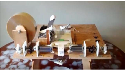
Figure 1. Bees Brothers Homemade Double Twist Candy Wrapper.
The most similar design that was found throughout the research process was the “Homemade Double Twist Candy Wrapper” design by the honey caramel business, Bees Brothers. This design, shown in Figure 1, follows a similar process of double twist wrapping a small piece of candy using identical rotating claws located on the opposite sides of the candy.

Figure 4. (a) Savage Bros Company Carousel Cream Center Extruder & Cutter including (b) the machine while operating.
The last design that was explored to help better understand industrial machines and further the focus on brainstorming was the Savage Bros Company Carousel Cream Center Extruder & Cutter. This machine, shown in Figure 4a, does not follow the same candy wrapping process as the previously mentioned designs. However, this machine provided insight on how to incorporate the initial cutting of the caramel. With a similar shape and consistency as the material shown in Figure 4b, the same function as shown in the device can be utilized to ensure that the final design can successfully cut the caramel into the necessary shape and size as requested by the sponsor.
OBJECTIVES AND SCOPE
The requirement for this project is to reduce the labor and time involved in the wrapping process. The final working prototype should be able to perform the following functions:
- Cut parchment paper to size
- Cut caramel into a specific predetermined size
- Fold and double-twist wrap the caramels within the newly cut parchment paper
- Wrap approximately 12 caramels per minute, or one batch of 144 candies in 12 minutes
- Perform these functions within a semi-automated process.
DESIGN DEVELOPMENT
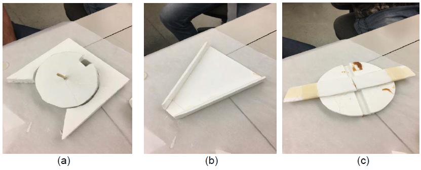
Figure 6. Basic material concept testing of (a) slotted wheel (b) extruding and moving the caramel (c) cutting the caramel with a wire.
Each idea was tested by making simplistic foam board models to observe simple functions of each idea. This step allowed for discarding unrealistic and impractical concepts to allow for a list of remaining sensible concepts that could be incorporated into the final product to allow for the machine to accomplish its task. Functions such as cutting the caramel, moving the caramel, cutting the paper, and placing the caramel in a slotted wheel and folding the paper as the wheel rotates around a wall were included in the functions that were tested through foam models.
PRELIMINARY TESTING
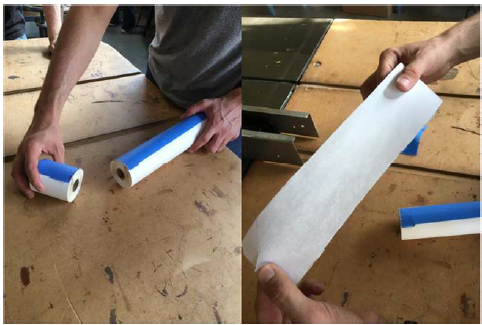
Figure 12. Roll of parchment paper cut with a vertical band saw.
The easiest option that had positive results was running the roll through a vertical band saw. Figure 12 shows the roll after being cut with this process. This would allow for a standard 15 inch roll to be bought from the supermarket and modified to fit the size needs of the candy. If a future version is necessary to adjust to different sized candies, this process could still be used to modify existing rolls of parchment paper to the proper size.
METHOD OF APPROACH
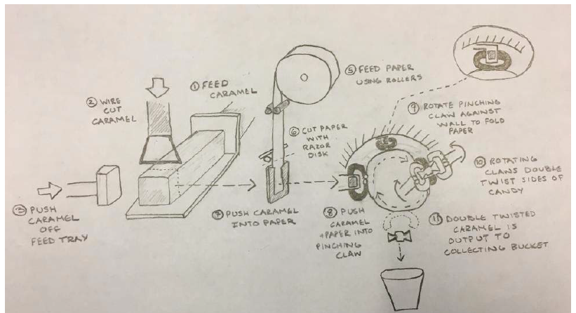
Figure 15. Full system layout C.
Figure 15. Full system layout C. The caramel is fed on a tray and cut by a wire cutter before being pushed into roller fed paper that is cut by a horizontal disc cutter. The caramel is placed into the paper and pushed into a pinching arm on a rotating disk that is rotated 180 degrees, which folds the paper around the caramel, and eventually wrapped by two rotating claws before exiting using gravity as the pinching arms open.
DESIGN DESCRIPTION
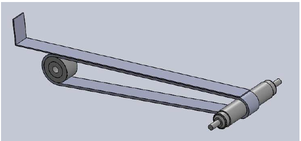
Figure 16. Feeding tray used to feed the initial strip of caramel.
The caramel will be fed into the machine on a specially designed tray, shown in Figure 16, that will be able to hold a strip of caramel candy. The tray portion that will be in contact with the caramel has been designed to be 12.08 inches in length and 0.75 inches wide and will be made out of sheet metal with a 0.048-inch thickness. The back wall of the tray will also be 1.2 inches tall to keep the caramel in place as the tray experiences an acceleration.
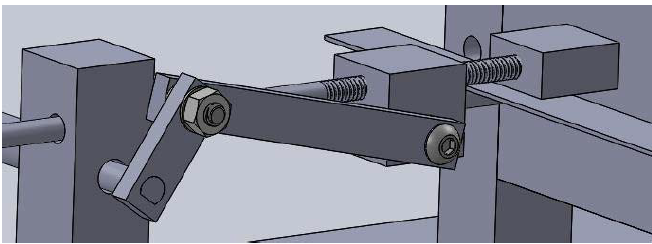
Figure 20. Pusher arm used to push the previously cut caramel into the parchment paper.
The two items, candy and paper, must be located together After the strip of caramel is cut into inch long increments by the wire cutter, the pusher arm from Figure 20 that is attached to a 2 bar linkage system will push the freshly cut caramel piece into the middle of the 3×4” piece of parchment paper. The caramel and paper is then pushed into the slotted disk pincher system that is spring loaded to catch the candy once it is pushed into the slot.

Figure 24. Geneva mechanism geometries utilized to design the Geneva gears in the final design.
The caramel must be moved throughout the machine The tray that the caramel will be loaded onto will be carried by a conveyor belt, which is driven by a Geneva mechanism that is designed to drive the belt that will push the tray in one inch linear increments towards the wire cutter. The Geneva mechanism was designed using triangular geometry shown in Figure 24.
POTENTIAL ISSUES
There are many concerns that are present as the building and testing phases approach.
The biggest concern for the upcoming testing phase is the potentially disastrous factors that exist such as friction, wear and fatigue throughout the gearing system. The timing of the functions will all be connected through a chain system that powers each shaft at a designated rotational speed. Even the slightest disruptions to the processes could be detrimental to the functionality of the whole machine.
Another potential issue is the unpredictability of the caramel as it is characteristically sticky. The stickiness of the caramel could result in jamming and not allowing the processes to function properly if the caramel gets stuck or warped.
MANUFACTURING PLAN
The material specifications for each full assembly were decided upon during the design phase of the project. FDA approved materials are required to ensure that the final design meets FDA standards. Research on plausible materials dictated that the materials chosen for the majority of the machine’s parts will consist of 6061 Aluminum, acrylic, delryn, and multipurpose 304/304L stainless steel.
Detailed descriptions of the materials chosen for each part can be found in Appendix G with the order sheet. This order sheet outlines the assembly part, item number, company, quantities needed and received, description, price, total cost, and ordered/received dates. This order sheet will help aid with organization and total cost of the materials ordered from online websites.
DESIGN VERIFICATION PLAN
Once the final product has been assembled, testing will need to take place to ensure that the machine can perform safely and correctly. Each function will be individually tested first to check for inconsistencies and possible malfunctions that would stop the design from carrying out the candy wrapping process.
The first tests will be conducted at slower operating speeds so the processes can be observed for possible problems. Once each function has been tested and the overall safety of each function design has been confirmed, a full system test with each function connected to one another will take place again with a very slow power input for observational purposes.
MANUFACTURING AND TESTING
The final design required many hours of manufacturing in the shops due to the unique quality of the parts that make up the machine. The raw food grade materials were ordered online before machining them to the required specifications. The following processes were utilized to create the individual parts for the final product;
- Mill and Lathe
- Drill Press
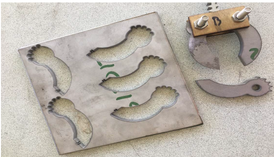
Figure 27. The claw arms were made using waterjet cutting to ensure a precise and quick process.
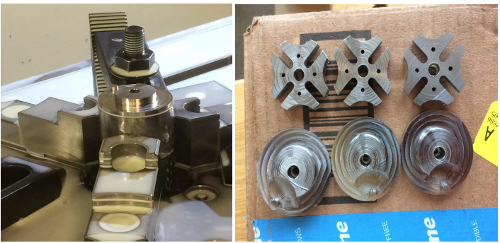
Figure 29. The intricate Geneva mechanisms and cam follower parts were created from the CNC machining process.
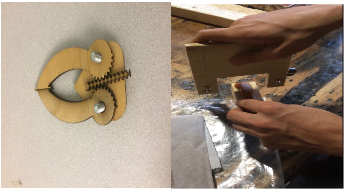
Figure 30. (Left) Claw mechanism testing prototype made from a laser cutter and (Right) wire cutting prototype to test cutting of the caramel.
Due to the manufacturing phase taking more time than we had initially planned for, testing of the various functions was postponed until a later date. However, testing of the various prototypes was completed to validate the designs of the parts. Although they were made from different materials such as plastic and wood, these can be considered valid tests since they were the correct size and proved the correct functionality of each of the mechanisms. The testing of these various prototypes allowed improvements and the ability to move on to the manufacturing of the parts from their actual material. An example of the tested prototypes can be found in Figure 30.
THE FINAL DESIGN
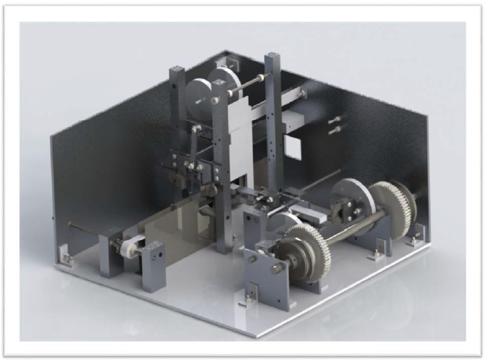
Figure 31. The final automated candy caramel wrapping design.
After nine months of researching, designing, testing, manufacturing and assembling, the final product was completed to the best of our abilities under the time constraint that we faced. Further manufacturing and testing will need to be completed before the machine can be completely assembled. Although the final product is still under development, the final CAD rendered version of the machine can be observed below in Figure 31.
SAFETY AND MAINTENANCE
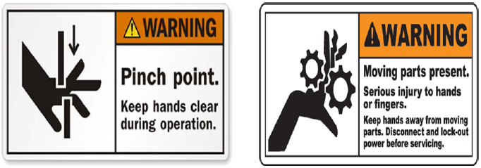
Figure 33. Warning labels associated with the possible safety hazards of the machine.
The most important aspect to keep in mind during the design process for a machine such as this one is safety. Safety consideration allowed for the inspection of the machine to locate the most threatening operation hazards, which consists of pinching points, sharp objects, and moving parts capable of crushing body parts if the operator is not careful. The warning labels from Figure 33 will be placed on the machine in order for those present when the machine is in use to be aware of the possible dangers.
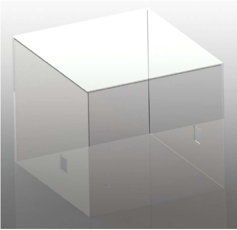
Figure 34. Acrylic housing designed to ensure safety.
In order to protect the operator and anybody else present while the machine is running, we designed an acrylic housing to completely cover the machine. This housing, shown in Figure 34, will protect against pinch points, moving parts, the wire cutter, the sharp razor that cuts the parchment paper and possible caramel projectiles.
CLOSING REMARKS
Overall, the process for designing an automated caramel candy wrapping machine proved to be both challenging and rewarding for every member of the group. Each one of us was pushed to grow as students and engineers in aspects such as critical thinking, creativity, project management, communication, design considerations and manufacturing practices. Countless hours were spent in the labs and shops feverishly working to meet our goals and conquer the challenges that seemed to constantly show up.
Although the project has not been completely finished, the progress that was made over the last nine months is evident from the advancements that have been made from a simple problem statement. The months of brainstorming, planning, testing, drawing, building and learning have all accumulated into the design that we have today that eliminates the need to wrap candy by hand.
In hindsight, there are a few changes that could have been made to allow for a simplified and less challenging experience. First off, designing and building a prototype out of plastic and allowing the designs to be given to a professional machine shop would have been beneficial. Second, understanding FDA guidelines better allowed us to realize that most of the metallic parts could have been made with plastics, which would have significantly decreased manufacturing time and costs. Lastly, designing parts that could be ordered instead of made from raw materials would have also assisted with the difficulty of the project.
We would like to extend a thank you our incredible advisor, Professor Lee McFarland, as well as our talented candy creating sponsor, Erin James. We could not have made the progress we did without the help and support that we received along the way from shop technicians and our fellow engineering students and campus staff.
Source: Cal Poly
Authors: Alexander Miller | Trevor Steele | Roman Stambaugh