EXECUTIVE SUMMARY
Daimler Trucks North America is creating an advanced emergency braking system which uses radar sensors that detect pedestrians and automatically applies the brakes to bring the vehicle to a stop. To improve and validate their technology, they need a mechanical pedestrian target that can mimic a human walking across the street. However, the assisted braking may not work properly during every test and the pedestrian target must be able to survive impact with a vehicle at low speeds. Four senior Mechanical Engineering students from California Polytechnic State University San Luis Obispo decided to take on the challenge.
The main features of the test dummy are as follows:
- The dummy’s shoulders, elbows, and hips articulate under active servo control to imitate human gait.
- The soft limbs can be crushed without permanent damage.
- The mannequin rests on a platform that is translated by a pulley system.
- The speed of translation and frequency of gait vary with separate analog controllers.
- The mannequin falls off the platform away from the truck upon impact.
- The dummy survives an impact without serious damage and continues to function.
This report details how this team of students was able to design, build, and test a prototype pedestrian test target shown below by Spring of 2017.
BACKGROUND
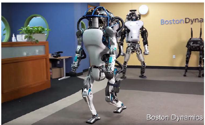
Figure 2.2.1. Atlas mid-stride.
Boston Dynamics created Atlas, a humanoid robot with high mobility and the ability to navigate rough terrain. Atlas controls its own motion and balance using Lidar sensors to adjust to variations in terrain. Atlas has near-human anthropometry and walks bipedally with the ability to lift, carry, and manipulate the surrounding environment with its upper body. Atlas has articulated, sensate hands that allow it to use human tools as well as 28 hydraulically-actuated degrees of freedom (“Atlas – The Agile Anthropomorphic Robot”).
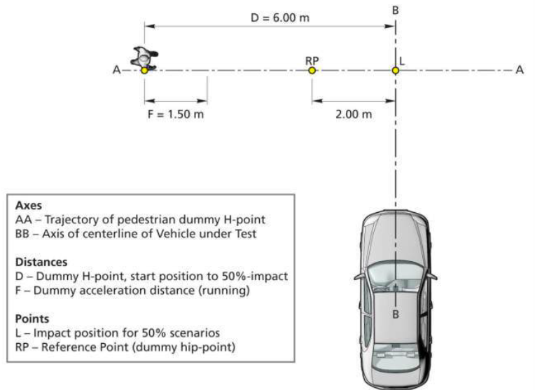
Figure 2.3.2. Test scenario and path for the Euro NCAP Pedestrian Target Car-to-VRU Farside Adult test.
There are specifications for pedestrian test targets that companies in the automobile industry may use by to qualify for a safety rating by certain third parties. The European New Car Assessment Programme [Euro NCAP] is one of those third parties; they originated in the UK and have created a voluntary vehicle safety rating system that details the requirements and testing procedure for pedestrian detection using Autonomous Emergency Braking Systems (AEBS).
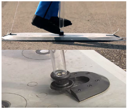
Figure 2.5.2. Top: 4Active Systems platform and flat belt pulley with a magnetic attachment between platform and dummy rod. Bottom: 4Active Systems platform with alternative notch attachment between platform and dummy rod.
4Active Systems currently sells a product that achieves the desired lateral movement without the large gantry crane setup employed by other designs. Their product allows a battery powered mannequin to be placed on a plastic pole that magnetically attaches to a moving platform. The platform is 25 mm thick with an angled edge to allow wheels to easily travel over it and moves on a flat belt pulley, which is shown in Figure 2.5.2.
OBJECTIVES
Meeting the customer’s specifications will allow Daimler Trucks to adequately test their collision mitigation system to be able to improve and implement them into their vehicles and thus save the lives of pedestrians across the world. Successful achievement of our primary specifications will ensure that the product we create for Daimler adequately mimics human motion, moves laterally in front of the vehicle at various speeds, is sufficiently durable to withstand impacts, minimize refurbishment, and is within budget. Meeting the other specifications, will make it easier for Daimler to use our product and allow for function in various testing environments.
DESIGN DEVELOPMENT
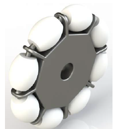
Figure 4.2.2. Omniwheels that can roll in two axes.
Changing Concept 1 to Concept 7 also replaced the single axis wheels with rollers that are able to roll both perpendicular to and parallel with the truck. The caster wheels in our initial concept were relatively tall, so we replaced them with omniwheels, shown in Figure 4.4.2, which can be inset. In addition, the arrangement of rollers on a main wheel allow omniwheels to change direction quicker than caster wheels, which track.
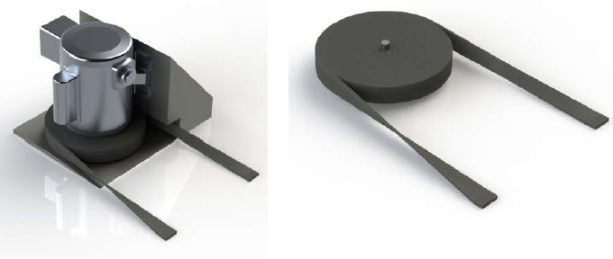
Figure 4.2.5. Belt and pulley system to drive lateral translation.
This system will incorporate a flat belt that the truck can drive over without causing any damage, which is currently planned to be twisted by the pulley housing. Furthermore, the belt and pulley system will have speed control based on the discrete voltage inputs to the motor driving the system. The belt will be sized so the platform will travel at least 10 m, which may require the use of tensioners.
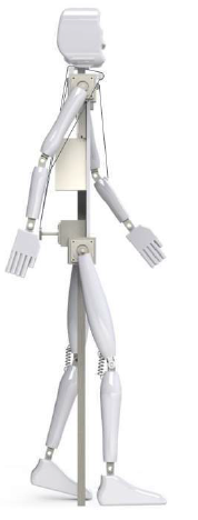
Figure 4.2.6. Side view of the mannequin showing mechanical tendon assembly.
The mechanical tendon, a wire attached just below the elbow on the inner forearm that goes around the shoulder to a motor, will also achieve correct elbow articulation based on placement on the forearm and attachment to the upper arm. In addition, the similar trajectories of the arm sections can be easily synchronized. Ideally, the tendon will attach to the same motor that drives the shoulder, but it may attach to a separate motor on the back.
PRELIMINARY PLANS
Preliminary Analysis Plan
We will begin our analysis by determining the weight of our mannequin and platform. Determining the weight will be an iterative process based on how material selections can affect our design, primarily in impact and stress, and secondarily in weight and cost. The Materials Engineering Consulting Club will assist in choosing a material which fulfills our requirements. This will allow us to size motors that we can then order early in the build phase as these will be long lead parts.
Analysis of the track system will include determining the loads on the track system in order to design and select a belt and pulleys that are capable of withstand the loadings. Our belt will be vertical as it goes around the pulleys and twist to ensure that the belt is parallel to the ground along the length of the track. We plan on designing either the housing of the pulley or a fixture that ensures the belt twists are the correct location to prevent any dragging of the belt. Due to the required length of the track, tensioners will likely need to be added to the belt.
MANAGEMENT PLAN
The success of this project requires that the team be organized and prepared. Team members bear responsibility for both tasks directly related to the engineering and creation of the product and also tasks necessary to facilitate work and communication. Secretary duties and responsibilities have been divided and are to be carried out for the remainder of the project.
Melanie maintains and organizes the information repository. Tiffany arranges team meetings, arranges the time, and reserving a location for team meetings. Chris and Tiffany will work together on being the team treasurer, maintaining and updating the budget for purchasing materials. Tim is the main point of contact for communication between team Crosswalker and the sponsor or outside resources.
FUNCTION DESCRIPTION
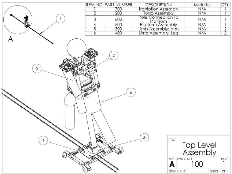
Figure 7.1. Top Level Assembly Drawing of the Pedestrian Target (Original design, prior to changing the direction of the platform and moving the control panel).
In our design, the 4 main subassemblies are the torso structure, limbs, platform, and lateral translation. These subassemblies interface and cooperate to create a pedestrian target that mimics the walking motion of a human crossing the street. The top level assembly displaying how the subassemblies are connected can be seen in Figure 7.1.
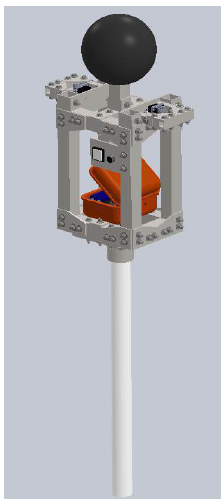
Figure 7.2. Torso Assembly (Original design, control was moved to the top of the torso to protect it from impact in a fall).
The torso assembly is able to distribute the impact loads across the structure and is primarily composed of 2 inch square tubing with a ⅛ inch thickness and steel plates that are ½ and ¼ inch thick.The entire torso assembly, shown in Figure 7.2, is the structure that houses the electronics, motors, and is the main source of impact resistance for our design. It is covered with fabric to give it a better human shape and prevent other fabric or wires from rubbing against sharp edges.
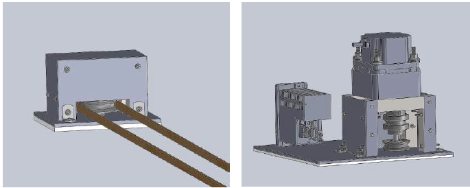
Figure 7.20 Isometric Views of the Lateral Translation Assembly Showing the Slave Side (Left) and Driver Side (Right).
The first four parts are the same as those used in the motor and pulley subassembly except that the shaft will be 3.25” long. The mounted thrust ball bearing will support the top of the shaft and is designed to mate with a ⅜” diameter shaft. The completed assembly of both sides of the lateral translation system can be seen in Figure 7.20.
PLANNED FABRICATION AND ASSEMBLY
Torso Structure
The stock materials used in the torso structure will be steel plates and square tubing. The tubing will be cut roughly larger than the specified size using a band saw; a milling cutter will be used to cut the tubes to size. To ensure alignment between mating parts, we will then use the end mill to cut holes into the square tubes. The triangles used in the body and shoulders will be made of steel plates.
We will use the band saw to cut the stock to the relative size. An end mill will be used cut the triangle shape and cut the holes into the parts. The main torso structure will be assembled using various bolts, all ⅜ inch diameter in order to standardize the process The base plate will be shaped using an end mill and several holes will be drilled. The holes that connect the bottom torso plate with the pole flange will be threaded using a ¾ inch hand tap.
Once all the parts are cut, the torso structure will be assembled using bolts. Expanded polyester foam will be attached to the torso structure. The process to do this will involve roughing the surface of the metal will 400 grit sandpaper, cleaning the surface and applying spray adhesive to the rough surface. The adhesive will be left to dry until the surface of the metal feels sticky. The foam will then be applied to the metal. The foam head will be attached to the neck tube using the same method. The servos will be bolted to the torso structure.
SAFETY CONSIDERATIONS
As is the nature of a collision with a 40 ton truck, safety is a large priority. To ensure that everyone involved will be safe, we designed our pedestrian target to mitigate possible hazards. There is a concern that there may be flying parts upon impact or that the 135 lb mannequin might hit someone during impact. Our solution to ensuring no parts will come flying off of the mannequin when struck is to cover the entire torso assembly with padding. This will make sure that any internal parts that could come loose will remain inside of the padding instead of being a projectile object. In addition, the padding will cover any sharp corners on the mannequin. This will help protect those handling the mannequin in the case that they drop it.
ANALYSIS FOR DESIGN
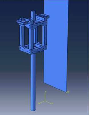
Figure 10.8. Finite element model of a truck impacting the test target structure.
A finite element model was used to simulate a semi-truck impacting a torso structure. This model is shown in Figure 10.8. Shell elements were used for each part of the test target structure since they require less computational time with little loss in accuracy. Solid elements could have been used, but the thin features of the tube structure could cause difficulties in meshing the assembly.
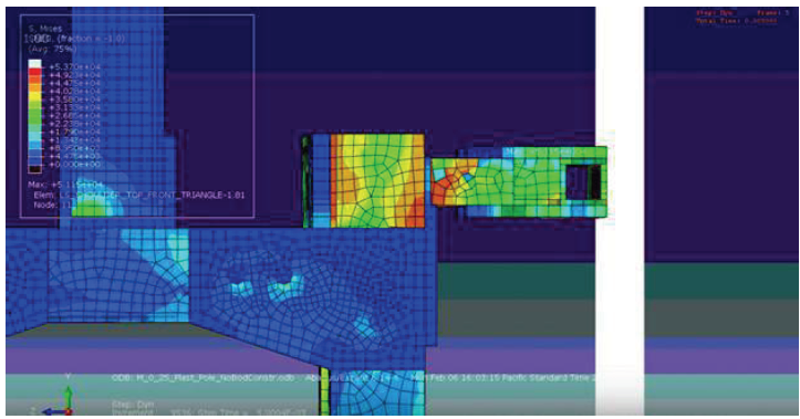
Figure 10.12. The initial impact.
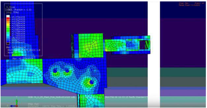
Figure 10.13. Five milliseconds after the impact.
As shown in Figure 10.12, during the impact there are stresses that exceed the yield stress of the material in the square tubing. The stresses propagate through the material and the bolt joints, as shown in Figure 10.13.
DESIGN VERIFICATION PLAN
To test and measure our pedestrian target and how it compares to our objectives and engineering specifications, we created a Design Verification Plan. The Design Verification Plan is a table that details our test plan to test each of the engineering specifications previously listed in Objectives, section 3 of the report.
Depending on the parameters and requirements, the tests will verify that our final product has met the objective either by pass/fail or specifying the acceptable range of the criteria. This verification plan lists the requirement to be met, the test description, acceptable criteria range, as well as the sample test quantity. The Design Verification Plan can be found in Appendix K showing the full details on what tests we plan on performing for a corresponding engineering specification.
COST ANALYSIS
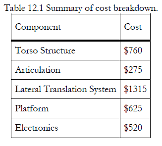
Our project is under budget after spending a total of $3,200 of the allotted $3,500. Most of the budget is being spent on the structure; the tubing, brackets, bolts, and nuts are used in nearly every aspect of this project and the amount quickly adds up. The other major contributor is the motors, with 4 high-torque servos and shafts costing $260 and the large DC motor for translation costing $520 with the motor and driver. The general breakdown of our costs are shown in Table 12.1. A detailed cost breakdown can be found in Appendix L.
MANUFACTURING
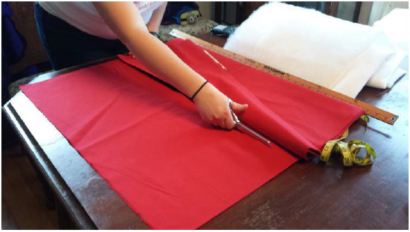
Figure 13.1. Cutting the fabric to size.
To create the limbs, canvas fabric was cut in a rectangular shape that would yield upper and lower limbs of the correct dimensions as can be seen in Figure 13.1. This was then sewn into a cylinder for the legs and a cylinder with reducing diameter for the arms.
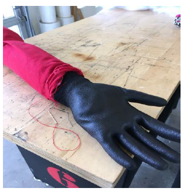
Figure 13.3. Attaching the hands.
Two grommets on either side of the limb were added just below the gathering. Mating holes sized for M4 bolts were drilled through the core. A M4 bolt was then bolted on through the grommets and the hole in the core to securely attach the limbs. The bottom of the arms were closed off by sewing a glove filled with batting to the end as can be seen in Figure 13.3.
TESTING
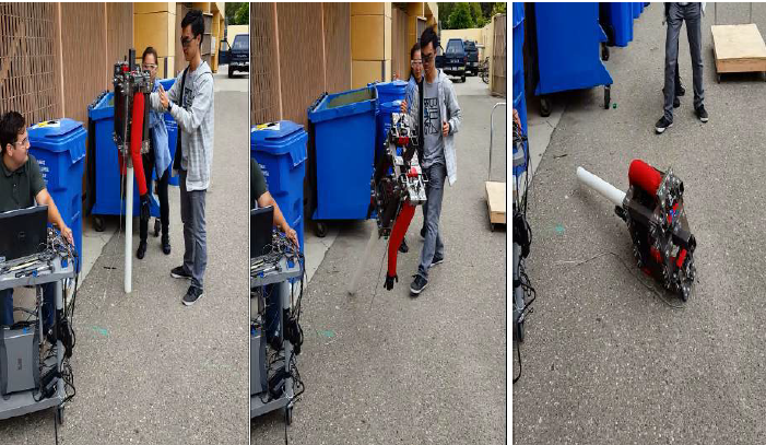
Figure 14.2. Test target falling on its side while testing with the strain gauge.
The strain gauge was configured in a half bridge circuit and the signal was sent to a Focus ll signal analyzer. The data was captured and saved using computer software. The test target was allowed to fall from a standing position with the help of a slight nudge, shown in Figure 14.2.
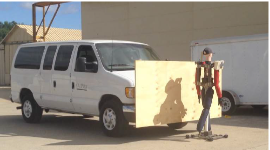
Figure 14.6. Impact Testing.
After we performed the analysis of the shoulder, we moved onto a larger test: hitting the mannequin with a van. We used a school van to impact the articulating mannequin placed on the stationary platform. We were able to see how the pole detaches from the platform and visually inspect the mannequin for damages after the impact. A metal ram with an added plywood board was attached to the front of the van to model the ram on Daimler’s freight trucks. This can be seen in Figure 14.6 as the van is just about to impact the mannequin.
PEDESTRIAN TEST TARGET OPERATOR’S MANUAL
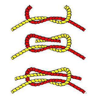
Figure 15.1. Square Knot Steps.
If the rope is not already attached, thread a loose end of the rope around both pulleys and tie the rope together using a square knot as seen in Figure 15.1. The square knot will be made twice should be closer to one end. The knot will be positioned underneath the platform to prevent the loops from going into the motor housings.
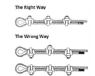
Figure 15.4. Correct Way to Create a Rope Loop.
Both free ends of the loop will be fastened to the one side of the translation system rope. Two rope clamps will fasten one free end of the loop in front of the platform and two rope clamps will fasten the other free end of the loop behind the platform. This will allow the system to be driven both forwards and backwards by the translation system. These rope clamps should be positioned such as in Figure 15.4 where the curved side of the U-bolt is facing the ground.
CONCLUSION AND RECOMMENDATIONS
The final product meets the customer’s requirements to be human-shaped, articulate its limbs like a walking pedestrian, translate across a road, and survive an impact. It does not achieve all of our more stringent engineering specifications and can be further improved, but a functional test dummy is ready to be handed to Daimler Trucks.
During the design phase, we chose to design the product to our modest manufacturing skills. This led to using bolts instead of welding pieces together. After manufacturing we found that for a structure with a large number of components to be assembled, welding would have been the proper choice. This would have saved a lot of time drilling holes, tightening bolts, and some alignment issues. In addition, welding may have allowed stress to be carried better throughout the structure rather than transmitting loads through bolted joints alone. In addition, we selected stainless steel for some uses where it was unnecessary, resulting in increased manufacturing difficulty and time.
An alternative design concept which could have sidestepped the aforementioned manufacturing issues is the lightweight crash test dummy. Our design uses strong materials and a rigid structure to survive an impact, but an early idea we had was to use light materials and a structure which purposely disassembled upon impact. We did not pursue this route because we did not have a good idea of how to combine the separating body parts concept with the necessity of actively controlling the limb motion.
Source: California Polytechnic State University
Authors: Tim Lee | Melanie Lim | Tiffany Prather | Chris Welch
>> Automobile based Matlab Project Topics with Free Base Papers Downloads
>> Huge List of Matlab Projects with Free Source Code
>> Matlab Projects Fingerprint Recognition and Face detection for Engineering Students
>> 200+ Matlab Projects based on Control System for Final Year Students
>> 80+ Matlab Projects based on Power Electronics for Final Year Students
>> More Analog Communication Projects using Matlab for Final Year Students