ABSTRACT
A four cable-driven parallel manipulator (4CDPM), consisting of sophisticated spectrometers and imagers, is under development for use in acquiring phenotypic and environmental data over an acre-sized maize field. This thesis presents the design, controls, and testing of two sub-systems in a 4CDPM: a Center of Mass Balance System (CMBS) and a Drop-Down System (DDS).
One of the factors that influences stability is the center of mass (COM) position of the end effector. An offset in COM can cause a pendulum effect or an undesired tilt angle. A center of mass balancing system is presented in this thesis to minimize the vibration and enhance the stability, accuracy, and quality of acquired data from the instruments.
The current design of the 4CDPM enables the sensing of the canopy at normal as well as oblique angles, but the end-effector itself must remain above the canopy; otherwise, the four support cables (and the end-effector itself) may impinge upon the crops surrounding those being imaged. Thus, a supplementary drop-down system is needed for positioning a small sensor package inside the canopy, which enables the researchers to analyze the low-height crops and take images of the side views of the maize canopy.
This thesis is divided into two parts, exploring both devices. Part one focuses on developing a system and method for the CMBS, while part two focuses on the feasibility of the DDS. In each part, the motivation behind each of the devices is described, and the design of the respective device and the reasons behind some of the design choices are presented. Several experiments are designed and executed for both projects, and the results are given for each.
For the CMBS, the results demonstrate that this system improves the stability of the end-effector by decreasing vibrations and static tilt angle. The results for the DDS show that this system needs an additional stabilization system to damp oscillations. Finally, the conclusion section describes the future work associated with the devices as well as the accomplishments achieved through the design of each device.
CENTER OF MASS BALANCE SYSTEM (CMBS)
An Introduction to the Four Cable driven Parallel Manipulator

Figure 2-1: Overview of the ETH Field Phenotyping Platform (FIP).
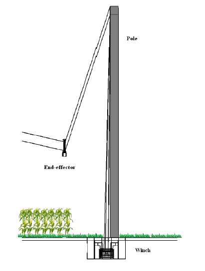
Figure 2-2: A schematic of pole, winch, and end-effector in the FIP.
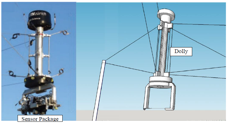
Figure 2-3: Sensor head of FIP carried by eight cables.
The FIP is an eight-cable driven parallel manipulator (8CDPM) for automated, image-based crop phenotyping, which is designed and built by the Spidercam Company (Figure 2-1). The FIP uses four winches that are positioned in each corner of the field near each pole. Two catenary cables are uncoiled from each winch to two pulleys that are mounted at the top of each pole in sufficient height (Figure 2-2). Pulleys constitute the points of suspension for the catenary cables carrying a dolly (Figure 2-3). The dolly carries the sensors using the pan-tilt unit (PTU). The PTU is able to turn the sensors in two axes, pan and tilt.
The Effect of End-Effector Oscillation on the Captured Images
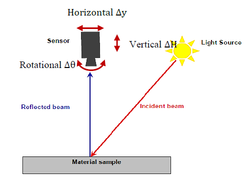
Figure 3-1: Movement of camera above the canopy in different directions.
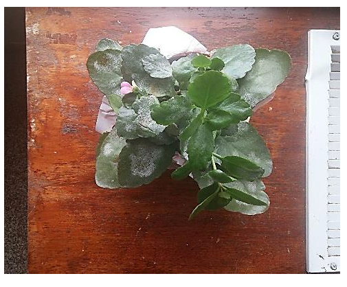
Figure 3-2: A clear image of canopy in stationary position of camera.
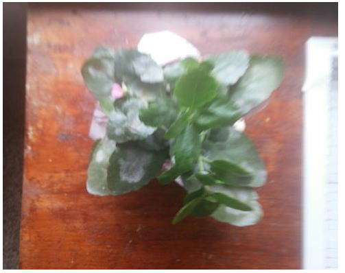
Figure 3-3: The effect of vertical oscillation of captured image.
Figure 3-1 shows the three main oscillation directions of a camera. When the end-effector is at a specific height above the canopy, a very small change in the position or orientation can cause a considerable error in the captured image of the canopy. Figure 3-2 and Figure 3-3 show the effects of vertical oscillation of the camera on the captured image compared to a clear image of the canopy from a stationary position of the camera.
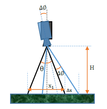
Figure 3-7: Error due to the rotational movement of sensor.
Motion blur in the captured image can also happen when the sensor slightly rotates as shown in Figure 3-7. Assuming x1 as the length of camera’s target area, and θ as the field of view of the camera, the governing relation for calculating the amount of blur due to change in the sensor’s angle can be found using a similar approach.
Center of Mass Balance System (CMBS)
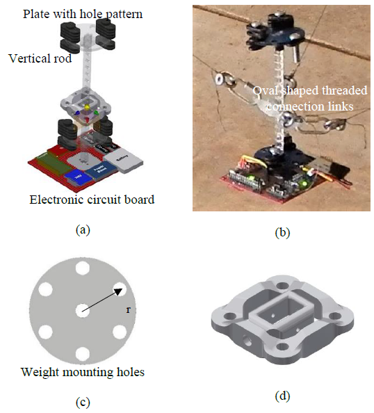
Figure 4-2: a) CAD model of the CMBS; b) Assembled CMBS c) Circular plate for weight mounting; d) gimbal system.
The Center of Mass Balance System (CMBS) consists of five main components, which are assembled by pins and screws: a vertical acrylic rod, two acrylic plates with holes, gimbal assembly, electronic circuit board, and weights. The assembled CAD model, as well as the fabricated CMBS, are shown in Figure 4-2a and b. Figure 4-2.c).
The top plate can be used to enhance the stability of the end-effector when the endeffector’s COM is below the cable’s connection point with or without horizontal offset, and the COM must be shifted to the center or near the center. The gimbal consists of two 3D printed frames: the outer one for the cable connection and the inner one for the vertical rod connection (Figure 4-2.d).
The experimental model used in this research is a 12th-scale hardware of the desired fullscale system (Figure 4-7). Dyneema fishing line (0.6 mm diameter) is actuated utilizing custom, miniaturized winches. Tripodal towers are used in place of guyed poles to allow for both rigidity and mobility of the support structures. Each winch assembly is controlled via RF communications with the system controller interface and run off of individual power supplies to allow the system to be easily repositioned and scaled.
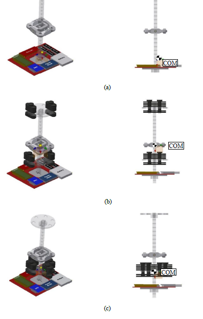
Figure 4-8: Position of COM in a) not using CMBS (58 mm below gimbal axis); b) using CMBS to move the COM onto the gimbal axis to the balance the end-effector; c) using CMBS to move the COM to 33 mm under the gimbal axis for the unbalanced test.
In the unbalanced case, the end-effector’s COM is moved to 33 mm under the gimbal pivot on the axis of symmetry. In the balanced case, the COM is moved to the pivot point on the axis of symmetry. The position of the COM for three cases of the balanced and unbalanced end-effector, and without using the CMBS is shown in Figure 4-8. As shown in Figure 4-8a, the COM had a small horizontal offset, which is removed after using the CMBS.
DROP DOWN SYSTEM (DDS)
Introduction and Motivation
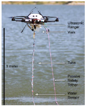
Figure 5-1: UAV-based water sampling.
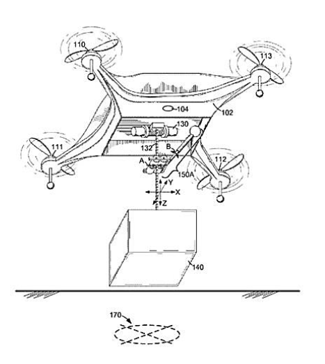
Figure 5-2: An Amazon sketch shows a tether system to lower packages to the ground.
An autonomous aerial water sampling system at the University of Nebraska-Lincoln was developed, which uses a lowered sub-system with two tubing systems for sampling the water from a lake or river (Figure 5-1). A similar system is also used by Amazon Company to deliver shipments to their customers in the shortest possible time. Figure 5-2 shows a tether system proposed by Amazon that lowers packages to the ground from a drone.
Initial Prototype and Dynamic Modeling
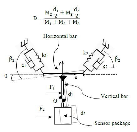
Figure 6-1: Two-dimensional model of the DDS.
Figure 6-1 shows a simple two-dimensional model of the DDS, which has three degrees of freedom. The vertical bar is completely connected or welded to the horizontal bar at one end and welded to the sensor package at another end. Two systems of spring and damper are attached to the horizontal bar which have the stiffness and damping constant of k and c respectively.
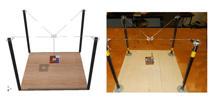
Figure 6-3: a) CAD model of DDS; b) Identical physical model of DDS.
Figure 6-3a shows a small scale computer model of the DDS, which is designed in the CAD software. Figure 6-3b shows the same physical model of the system. The stiffness and damping constant of each spring are 33.75 N/m and 0.026 N s/m respectively. Poles are each 46 cm and the field area is 52 cm × 47 cm.
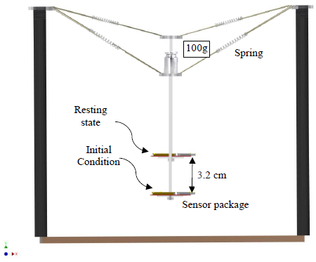
Figure 6-6: Applying the initial condition.
The initial condition for starting the experiment is obtained by putting a 100g weight on the cable connection plate, which lowers the end-effector 3.2cm (Figure 6-6). This initial condition is also applied to the computer model before starting the system to oscillate.
Design and Analysis of Full-Scale DDS
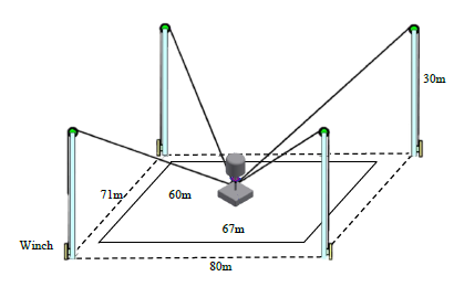
Figure 7-1: Real size phenotyping field for mounting the 4CDPM.
The initial condition for starting the experiment is obtained by putting a 100g weight on the cable connection plate, which lowers the end-effector 3.2cm (Figure 6-6). This initial condition is also applied to the computer model before starting the system to oscillate.
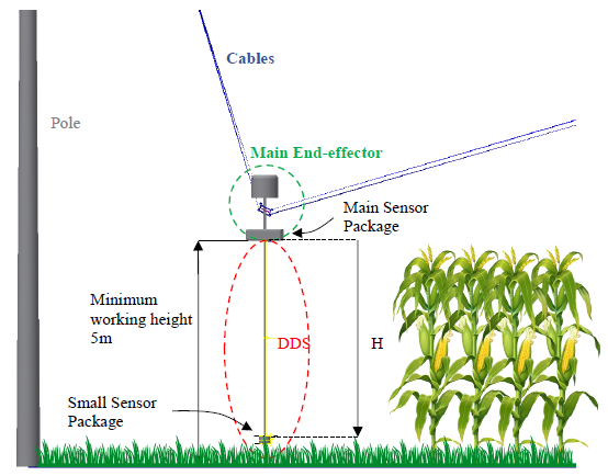
Figure 7-5: side view of DDS in the field.
The experiments are done in four positions of the field shown in Figure 7-4 where point 1 has the most symmetric cable tension, and points 2, 3, and 4 have the most asymmetric cable tension. In each position, the drop-down system (DDS) starts working when the main sensor package is placed 5 m above the ground near the canopy surface (Figure 7-5).
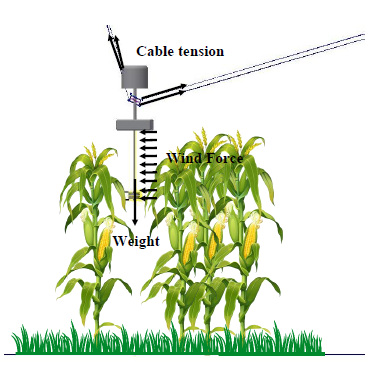
Figure 7-6: Free body diagram of DDS.
Finally, the software calculates the vibration of the small sensor package in three dimensions and stores the vibration amplitude and speed data in separate spreadsheets. A free body diagram of the end-effector is shown in Figure 7-6 for better illustration.
Small Scale Prototype of DDS
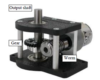
Figure 8-1: Worm gear box.
Worm gear configurations in which the gear cannot drive the worm are called self-locking. Therefore, the motor does not need to be used to hold the weight of the small sensor package while it is scanning the plants at a specific height or is maintained in the sleep mode near the main sensor package. A 30:1 ratio worm-drive gearbox (Figure 8-1) is used to self-lock the system in the sleep mode.
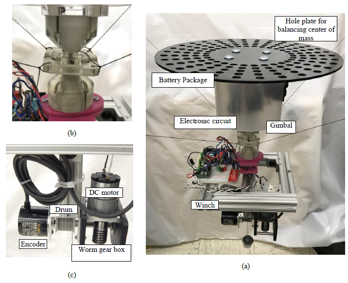
Figure 8-5: a) DDS model assembly; b) Gimbal system; c) Drive system.
The final assembly is shown in Figure 8-5a. A plate with a circular pattern of holes is connected on top of the battery package where the extra weights can be mounted to balance the COM. Figure 8-5b shows a gimbal system that is used for connecting the cables to the end-effector. The motorized driving system (Figure 8-5c) uses the self-lock worm gearbox to prevent the batteries from draining power when the small sensor package is in position for scanning the plants. The battery package provides enough power for running the microcontroller and the driving the winch system.
Discussion and Conclusion
This thesis presents the design and testing of two subsystems for the end-effector of a 4CDPM. In Part I, a center of mass balancing system was presented to minimize the vibration and enhance the stability, accuracy, and quality of acquired data from the instruments in the sensor package.
The sensor package is one of the most important parts of the end-effector of a 4CDPM, which consists of a variety of sensors and electronic devices with different sizes and weights. Researchers sometimes need to add, remove, or swap sensors in the sensor package to reach their sensing objectives. Any changes in the position of components inside the sensor package can change the COM of the whole end-effector resulting in instability during movement.
To prevent this, an easy to use passive system was designed, which enables researchers to adjust the COM simply. The described system provides this ability using two circular plates with a pattern of holes for weight attachment and a rod for mounting the circular plates in different heights. A combination of weight arrangements with plate movement along the vertical rod provides enough resolution for COM adjustment. Researchers can use the proposed COM finder apparatus and automated computer program to locate the weights in the best position.
Source: University of Nebraska
Authors: Iman Salafian
