EXECUTIVE SUMMARY
This final design report will detail the entire engineering design process from conceptualization through manufacturing and testing. After introducing the topic and scope of the project this document presents all of the benchmarking and research performed in order to obtain as much information about similar current products and possible solutions. Next the objectives of the project are presented where the needs are transformed into engineering specifications that will guide the design of the product.
Design developed is then presented with ideation, idea evaluation and selection, analysis, manufacturing considerations, and final design selection. The final design is then presented with each of its three subsystems, including supporting analysis, manufacturing and testing plans, bill of materials and cost as well as material selection, safety considerations, and maintenance plans. Following that is the management plan where team roles are outlines and project deadlines are presented.
Product realization is next, which includes the manufacturing process that was taken for all components as well as description of changes between the planned and built design and recommendations for future manufacturing changes. Design verification follows with testing procedures and results and a final budget for the manufactured design. Next are conclusions that summarize what was done during the project and recommendations which outline what could have been done differently from a design or project standpoint to provide insight for future designs. References for all researched information are included in order cited throughout the document. Finally all appendices are included at the end of the document that were referenced throughout the report as well as other important information.
BENCHMARKING
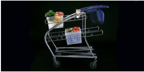
Figure 3: IDEO Shopping Cart.
The cart, in Figure 3, also had dual child seats with a play surface, allowing parents to feel more comfortable taking their small children shopping. The most notable change from a traditional cart was the removal of the large central basket, replaced by many smaller plastic baskets. While this allows for more shopper flexibility, it reduces the carrying capacity of the cart overall, discouraging use from contractors, construction workers, or any other type of laborer.
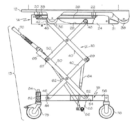
Figure 7: Scissor Mechanism with Detachable Top.
Ferno publishes a public list of their patents on their main web page, which is where we found a patent for a previous model of the Salesmaker cart. It is similar to the removable top design presented previously, but in this case the base is designed as a multi-link scissor mechanism that supports the weight and allows for height adjustability. Shown in Figure 7, the scissor mechanism is actuated with a worm gear and handle that allows it to be raised and lowered even with weight on the top.
BACKGROUND
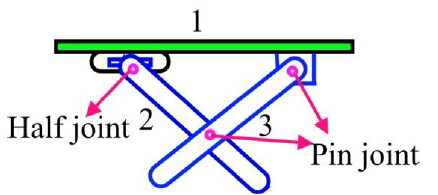
Figure 9: Ironing Board Joint Diagram.
The scissor lift mechanism works under the same principle as an ironing board, which is one of the first things we looked at as a simple collapsible/raising/lowering mechanism. As Figure 9 shows, it is a simple mechanism with a fixed pivot at one end, a sliding pivot at the other end, and a fixed pivot connecting the two legs together.
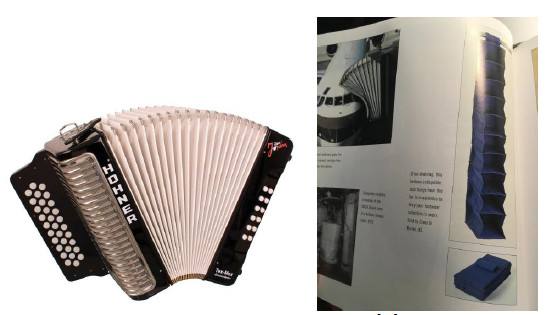
Figure 17: Accordion Designs.
Another mechanism similar to the scissor is the accordion mechanism, shown in Figure 17, that uses some sort diaphragm or folded material with or without an inner skeleton to achieve the same purpose of a large expanded area with a minimum collapsed one. An interesting aspect of accordion designs is that they do not have to be completely linear, they can expand on a radius as well as linearly which gives them more freedom than other mechanisms.

Figure 28: Linear (Left) and Angular (Right) Ratcheting Mechanisms.
Another option for locking and adjustment is a ratcheting system that would allow the device to move in one direction freely, but automatically lock if it were to move in the other direction. A ratcheting system is safe and automatic, it does not require user input to engage, only to disengage. The resolution of the system can also be very small allowing for fine adjustment when the notches are placed close together. Figure 28 shows a simple linear and radial ratcheting system which can lock linear and angular motion respectively.
OBJECTIVES
Needs List
In order to find the engineering specifications that we would use to guide the design of our product, we first had to determine what the customer needs and requirements were. In order to do this, we interviewed our sponsor who is our main customer, as well as retail shoppers, and used our own experience.
From this we were able to generate a list of non-technical needs and requirements from the users of this product. The requirements and needs we determined are as follows: safe, reliable, large volume capacity, simple design, low cost, light-weight, durable, large load capacity, customizable personal aesthetic, maneuverable, ergonomic, easy to operate, versatile, adjustable, easily manufactured, and low maintenance.
DESIGN DEVELOPMENT
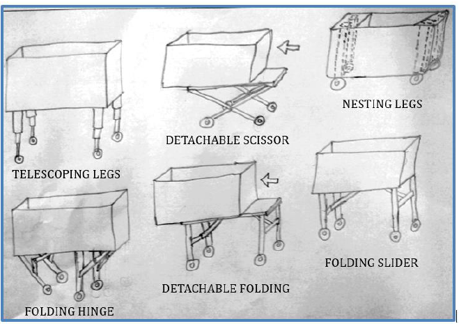
Figure 29: Top Six Stowing Mechanisms.
The stowing mechanism allows the cart to collapse into a low-volume module that safely stores goods in the storage area of a vehicle. After a complete brainstorming session, our team identified six ideal stowing mechanisms for our cart shown in Figure 29.
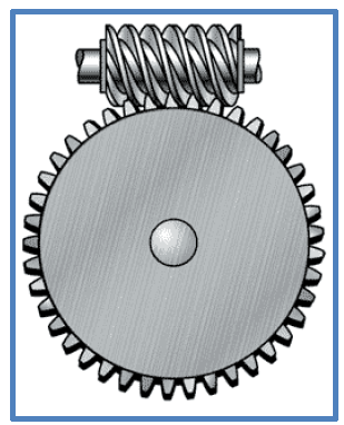
Figure 32: Wheel and Worm Gear Mechanism.
A worm gear allows for a large gear ratio, reducing the amount of torque from a gear. This could allow a rather weak shopper to lift a rather heavy load, ideally directly into the shopper’s car. A wheel could be present on the outside of the utility cart for a simple user interface with only one degree of freedom. A simple drawing of a spur and worm gear mesh is shown in Figure 32.
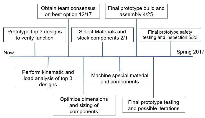
Figure 38: Preliminary Construction and Testing Timeline.
We will then complete all the necessary machining and assembly before the midway point of spring quarter, April 25, 2017. This will leave us enough time for component level testing and iterations as well as final system level functional and safety testing to be completed before May 23, 2017. Upon sign off of the safety and functional testing the device will be completed and handed over to the sponsor for personal use. Figure 38 shows a timeline with the most relevant dates. A more in depth Gantt chart is included in Appendix C.
FINAL DESIGN
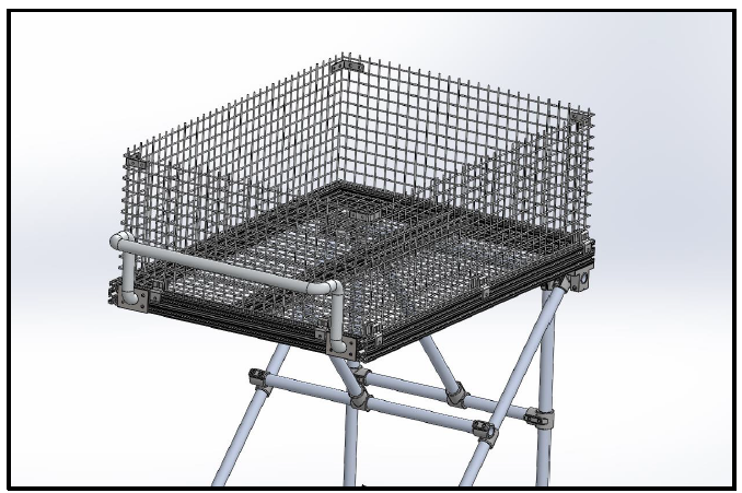
Figure 39: The basket & handlebar subsystem for the 80-20 T-Slot frame.
The galvanized steel wire mesh basket, constrained by galvanized steel corner brackets near the top of each wall and 80-20 wire panel holders at the base of each wall, acts as a rigid body to safely contain the items belonging to a customer. The handlebar is connected to the frame with 4 fasteners attaching a thin steel welded plate directly to the 80-20. For the sleek steel frame, the handlebar is simply welded directly to the back of the frame.
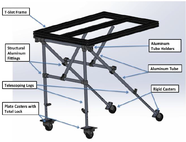
Figure 40: Frame and Folding Mechanism.
Figure 40 shows the pivot point as well as the extended and folded positions of the legs. There will be four legs total, two in the front and two in the rear, each of the two front and rear legs will be connected together with a horizontal support which will increase the rigidity of the structure as well as function as a mounting position for the slider bar.
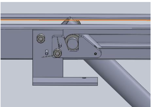
Figure 46. Straight View of Locking Mechanism.
The sliding and locking mechanism shown in Figure 45 with a close-up in Figure 46 facilitates the action of allowing the legs to fold up and down in a controlled manner. It also locks the legs in the upright position and controls the release of the legs when the cart is being stowed into a vehicle. The sliding mechanism consists of a track, a follower, and bar which sits in the track.
MANAGEMENT PLAN
Our management plan involves assigning specific team roles to each member regarding the types of work that they will be completing for the quarter. Each new quarter, we will be redistributing the team roles to give every member a fresh experience as well as making sure the workload is balanced for everyone.
- Team Roles
- Project Deadlines
PRODUCT REALIZATION
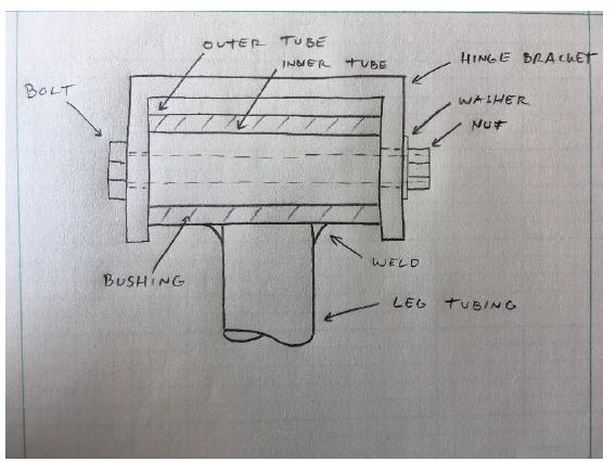
Figure 49. New hinge design to save material and money.
The hinges that would mount the legs were then manufactured by cutting pieces of angle iron and welding them in the center to create a U shape. The hinge then was drilled in the center to provide clearance for a mounting bolt. Supporting brackets had to be made for both the front and rear hinges to ensure structural rigidity and place the hinges inboard of the rectangular tubing.
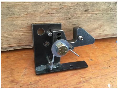
Figure 61. Fully assembled locking mechanism.
The locking mechanism was custom made from raw materials starting off with thick and thin steel plate. The components were cut out using the water jet to achieve a precise profile and accurate dimensions with minimal post processing. The parts were then drilled using the drill press and mill. The bracket was also welded together using TIG welding to reduce heat input and warpage. Springs, dowel pins, nuts and bolts were purchased and the entire mechanism was assembled and mounted to the sliders in the appropriate location.
DESIGN VERIFICATION
Test Descriptions
Our final product has five functional tests to ensure the safety and reliability of the
personal utility cart, as desired by our specifications. The tests include: load capacity
test, subassembly test, folding test, locking test, and maneuverability test.
- Load Capacity Test
- Subassembly Test
- Folding Test
- Locking Test
- Maneuverability Test
CONCLUSION AND RECOMMENDATIONS
The results of this project include research into the personal shopping cart market as well as a prototype of a folding cart. The cart has a steel frame and can easily support 200lbs of anything that can fit into the basket. We made removable wooden basket for the top of the cart, which allows for items to be transported easily. The cart should be able to handle day-to-day activities such as groceries as well as carrying around tools or building supplies.
One problem with the cart is that we ran into an interference problem that we were not able to fix before the deadline. The problem was in the locking mechanism clearance inside the rails. This problem should be an easy fix as the locking mechanism can be mounted on the outside of the rails instead of the inside. One of the challenges with this project was the amount of time required to fabricate all of the components. Our team manufactured almost all of the components which was very time intensive. Given more time this problem would have been sorted out better.
Once the mechanism is moved to a location where it will not interfere, the cart will be able to lock upright. This cart can be made fully functional, however it is still not a consumer grade product. This project started as a way for us to look into this and come up with a design that could be made into a product used by consumers. The outcome of having a prototype cart is still a useful step in designing a finished product. In addition to the prototype, the research and analysis and the design criteria found in making this prototype are useful in designing a final product.
Through the sponsorship of Cal Poly Mechanical Engineering graduate Michael Allwein and Professor Sarah Harding, we were able to design and build a utility cart with folding legs. We hope this project will aid in designing a product that can end up being sold to consumers and help people make getting their groceries around simpler.
Source: California Polytechnic State University
Authors: Eric Johnson | Jason Munter | Sean Portune