ABSTRACT
This thesis work was done in order to improve the capabilities in a preliminary aircraft analysis program, DIBA, at Saab Aerosystems. The areas that this was done are in the sizing and balance. One sizing tool was developed in order to make a performance analysis with the DIBA generated geometry and customer and/or regulation based criteria. A balance diagram, a neutral point estimation function, a landing gear plot and a trim program was created in order to extend the weight and balance analysis.
Results show that various aircraft both military and civil can be analyzed with good comparison to other analysis and reality. For example EXCEL implemented analysis and graphs over real aircrafts shown in the report.
PRESENTATION
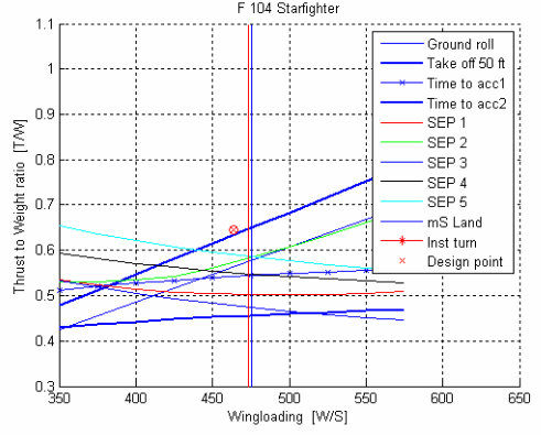
Fig 3.1 Sizing diagram
To create an overall picture of the airplane requirements, a so called sizing diagram is drawn. In this diagram different requirements are plotted and the aircraft is plotted at the design point. The graph below shows a general sizing diagram. All the requirements will be described later in more detail. The airplane sizing graph plotted below is for the Lockheed Starfighter F104. The first aircraft designed for sustained flight above Mach 2.
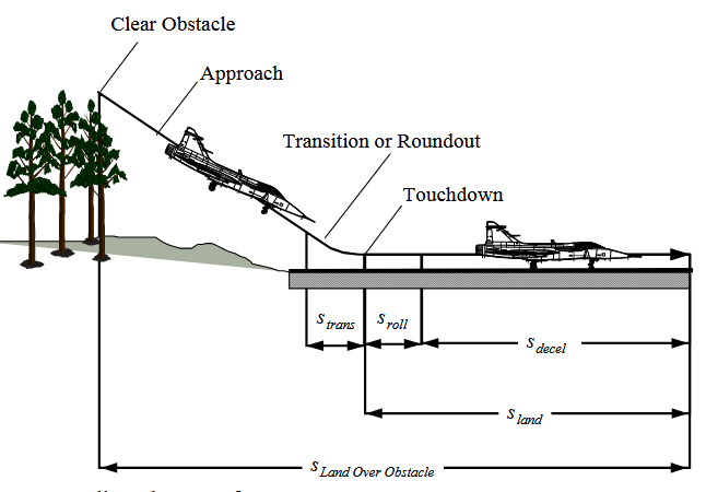
Fig 3.2 Landing phase
Landing is in a sense takeoff in reverse. Instead of increasing speed until transition and climb one descends to transition and decelerates to stop. The landing requirement in FAR 23 and 25 that was implemented in the sizing tool came from Ref 1, Torenbeek. It is there stated that the approach speed should at least be 30% more than the stall speed. That is: VA =1.3 VSL. The stall speed is that in the landing configuration. The landing distance is related to the square of the stall speed. This in turn can be used to determine the wing loading of the aircraft. Since no thrust is accounted for during this phase this requirement is only W/S dependent.
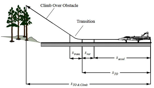
Fig 3.2 Landing phase
A certain distance is desired by the customer when the aircraft should be able to leave the ground. This distance is defined in the Takeoff ground roll, when the main wheels are in the air. To reduce this distance one can increase the lift, either with a larger wing or advanced lifting devices, or a greater thrust to weight ratio.
ANALYSIS
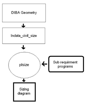
Fig 4.1 program structure
The Civil sizing tool is designed to be a sub function to analyze an aircraft in the preliminary design MATLAB program called DIBA. All the requirements previously described were implemented in a MATLAB function called plsize that plots the different curves and the design point of the aircraft. One sub function for each requirement was used to calculate the data needed for the complete sizing diagram. In the beginning of plsize an initiating value function called indata_civil_size was used.
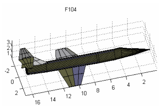
Fig 4.16 F104 Starfighter slim
On deciphering these values the speed is highest on the second time to accelerate and the first SEP requirement. The difference in the methods is greater with high mach numbers for the thicker geometric presentation of the F104. This also seems to be the case in the sizing diagram. So far during this investigation, the F104 has been calculated with the intake area included. In reality some of the air that flows here does not contribute to the total drag because it is sucked into the engines. Below a picture of a Starfighter without the intake area is displayed
In the preliminary aircraft calculation program DIBA it is possible to make a three plane view of the aircraft. This was shown in the analysis of the sizing tool where the Saab 2000 was displayed. Since the landing gear program was created using the Jas 39 Gripen airplane this will be shown as the first example.
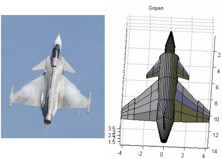
Fig 4.20 the picture was taken from the Czech air show 2006
A three plane view of the Jas 39 Gripen is displayed below
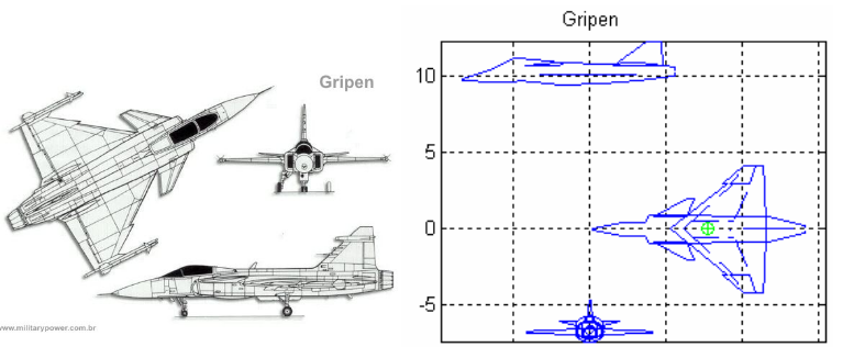
Fig 4.21 Three plane view of Gripen, Left
CONCLUSION
The work that has been done deals with the early phases of aircraft development. Therefore it is not of use to spend too much time on detail in one part rather to look at the aircraft as one part and research many different approaches.
Adaptable modules and functions have been created to be able to size and balance an aircraft in the conceptual phase. They are illustrative and easy to understand.
For the sizing, there are a lot of assumptions that needs to be made in early designs in order to make a preliminary estimation of the aircraft. So the level of accuracy is never very high. What one can do is to see which requirements are driving and see if they can be met or not. Accurate performance analysis is more in the field of detailed design when a concept has been chosen. Not necessary full scale testing, but more rigorous simulations with stronger software and more accurate variables as indata will then be used.
In the military sizing, some other measures of merit can be considered. If the behavior is unpredictable at high angles of attack, the combat effectiveness will be affected and turn rate alone cannot describe this. These criteria were not taken into account in this study.
To know the weight and balance are of outmost importance and the simple graph generated in the program above can be of great help to keep track of the c.g position.
The neutral point is only estimated roughly in this program. It gives a picture of what to expect when one changes the lever arm or the size of the horizontal surface.
A lot of indata is needed in order to calculate the parameters needed to trim the aircraft. Many of them have to be estimated very roughly with assumptions or empirical formulas. This means that one cannot expect a very high degree of accuracy. The tests show reasonable values for deflection within normal configuration usage.
FUTURE WORK
Looking at the sizing tool it would be of interest to have a more graphical interface. A user friendly faster link so changes can be made and the result recalculated and plotted again with the push of a button.
It would be useful to develop an optimizing system between variables. This could for example mean that a certain mission is flown with in a loop with different wing layouts and the most favorable is stored in a file.
The sizing requirement time to climb could use better methods to choose which absolute height to use for each aircraft type.
If one tries to implement a lifting tail/canard or a tandem wing system one runes into trouble due to geometry definition in the programs. Also with a Blended wing body configuration. With some effort, a generic code could adapt and calculate the neutral point for example.
Source: Linkopings University
Author: Gustav Peterson
>> Matlab Project Pdf Free Downloads for Aeronautical Engineering Students
>> Automobile based Projects for Final Year Engineering Students
>> MATLAB based projects for Mechanical Students