PROBLEM AND OBJECTIVE
Lexmark presented a problem in the design of their printers concerning the gear train that drives the agitator shaft in the developer unit. This unit is the housing for the toner that is used to create the print on the paper; this setup can be seen in Figure 1. The problem was further investigated and was determined to be that the resistance load provided by highly compacted toner in the developer unit was much too high at around 350 mN-m, leading to both tooth disengagement, or cogging, and teeth breaking off of the agitator driving gear and off of the small gear of the compound idler gear. This was defined to only occur during initial startup as the agitator shaft stirred the compacted toner, which would greatly reduce the load.
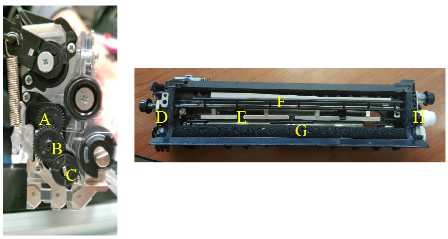
Figure 1 Setup of Developer Unit with (A) Agitator Driving Gear (B) Compound Idler Gear (C) Agitator Driving Gear Train Input Gear (D) Gear Face Plate and Agitator Shaft Bearing (E) Agitator Shaft (F) Auxiliary Paddle (G) Toner Roller (H) Input Driving Gear.
DESIGN REVIEW
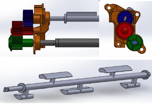
Figure 2 Final CAD Assembly Front View, Side View, and Paddle View for Increased Gear Face Width and New Paddle Shape.
The paddle shape change was estimated to reduce the load to as low as 112 mN-m of torque based on calculations using coefficient of drag. The final design can be seen in Figure 2; the total factor of safety of the final design if the load was reduced completely was 2.6 and if the load was reduced half as much as expected due to incorrect assumptions.
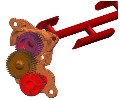
Figure 3. Final Design Adjustments: Reducing the Internal Hub and Agitator Shaft Length.
The agitator shaft length was originally elongated to fill the length of the increased gear face width, but, due to manufacturing issues, the internal hub of the gear and length of the agitator shaft were reduced to be the same length as the original gear, as is shown in Figure 3. Note that this would also reduce the overall shaft deflection and the gear would have to be molded this way to keep a constant wall thickness.
EXPERIMENTAL SETUP
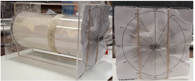
Figure 4. Load Reduction due to Agitator Shaft Paddle Shape Test Apparatus and Notched Loading Beam.
The first test conducted was designed to determine the actual reduction in load provided by the change in shape of the agitator shaft. To save money and ease testing difficulty, compact flour was used as to represent toner in the system in conjunction with the test apparatus seen in Figure 4.
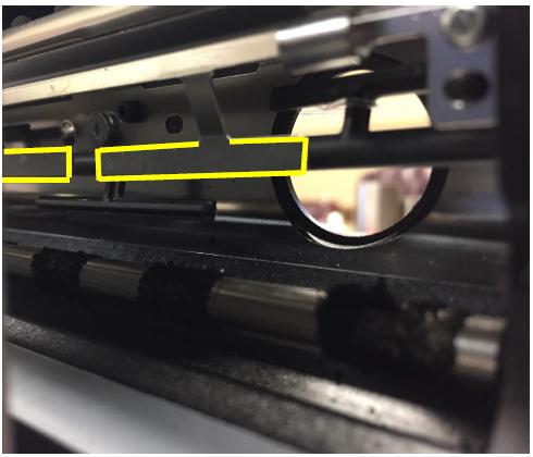
Figure 7. Developer Unit with Metal “T’s” Highlighted to Show What was Removed for the Alternative Test 4: Final Design Assembly Test.
Upon completing the first four designed tests, an additional test was developed. The final design assembly test was redone with the metal “T’s” within the developer unit removed; these “T’s” are highlighted in Figure 7. This was done to attempt to discover the actual load of the toner alone without any potential interference from this alternative part of the system. Other additional tests were discussed but were not able to be run due to time constraints.
PROCUREMENT, FABRICATION, AND ASSEMBLY

Figure 9. Gear Failure Test Failure Modes with (A) Molded Gear Failure and (B) Molded, Old Design Machined, and New Design Machined Agitator Shaft Failure.
First, the molded gears were found to fail under the original setup at about 98 mN-m which was 26 mN-m more than predicted; this failure is depicted in Figure 9. Second, both systems with machined gears and shafts were found to exhibit a preloading phenomenon that manifested itself as a 90° to 120° visible rotation of the end of the agitator shaft that engaged with the agitator gear, along with a large vertical deformation of the central portion of the agitator shaft of about roughly 3.5 mm, calculated from images.
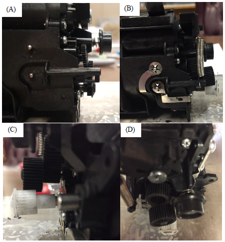
Figure 11. Example Deflection for (A) Original Design Output Gear at 137 mN-m, (B,C, and D) New Design Idler Gear at 158 mN-m.
Finally, the deflection of the gears was observed for both the old and new design as is depicted in Figure 11. Note that the images for the deflection of the new gear train design were taken during a test run where the input gear was improperly assembled on the input shaft, resulting in a reduction of tooth engagement.
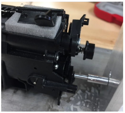
Figure 12. Gear Failure Test with Reduced Deflection Trial Run with Steel Shaft and One Aluminum Support Pin at 112 mN-m Load.
The third test was also conducted with molded gears of the original design, machined gears of the original design, and machined gears of the new design. However, to avoid the agitator shaft failure found previously, a steel shaft was machined to fit in place of the agitator shaft and fixed from rotation; due to the increased strength of this shaft, deflection of this shaft was predicted to decrease greatly, so only one of the aluminum support pins was used, as can be seen in Figure 12.
CONCLUSIONS
Overall, the objective to innovate the gear train such that the system would be able to accomplish ten startups with a resistive torque of up to 420 mN-m where each startup was defined as ten complete revolutions of the agitator shaft while maintaining the original functionality was not accomplished. The system was found to have three additional problems: the agitator shaft was found to shear at the point of stress concentration at a load 127 mN-m of torque ± 35 mN-m, the idler post was found to shear at the point that it connected to the gear face plate at a load of 140 mN-m of torque ± 38 mN-m, and the agitator shaft was shown to be deflecting to the point that it would interfere with the metal “T’s” fixture under a load of as low as 23 mN-m.
It was estimated that the change in paddle shape would reduce the maximum torque required to drive through the toner by about 10%. The load of the toner was defined to be greater than 174 mN-m, with the maximum load not reached. Furthermore, it was found that the machined gears were at least 27 % stronger than the original molded gears. With this increase in strength, the machined gears were not able to reach failure due to the new failure modes being very close behind the original gear failure mode presented around 30 mN-m so the impact of the gear design change was not directly determined. Finally, a preloading phenomenon was identified within the system.
Source: University of Tennessee
Authors: Jay A. Crist | Sarah Gore | Kun Xie | Michael Mixoon
>> Autocad based Mechanical Projects for Final Year Students