EXECUTIVE SUMMARY
The aim of this project was to develop a more automated process for drawing and twisting of graphene fibers than was currently in place. This was implemented by having two chemical baths with variable speed rollers at either end, and intermediate roller to spool fiber between stages, and a twisting cylinder with integral spool to twist the fiber as it is collected. The goal was to have this first iteration deliver a working prototype, however due to manufacturing delays and timing constraints, that will be missed. A second follow-on project would be able to continue the work presented here and fulfil the stated aims of the project.
The bulk of the structure is fabricated from PVC pieces waterjet cut from a large sheet. This allowed for quick manufacture of most pieces in the design. From there, some secondary machining was done to add mounting and fastening locations. PVC pieces were attached to one another primarily through the use of #8-32 screws with washers and a brass threaded insert.
Due to PVC being a soft material, tapping threads into it directly was avoided. The baths were sealed mostly with an automotive gasket compound to permanently seal one half, while one wall was sealed with a silicon gasket laser cut from a sheet. This makes the bath wall removable for maintenance. Two baths were made to allow multiple stages of drawing or one coagulation stage immediately followed by a drawing stage.
From the drawing, the fiber advances to the auxiliary roller. The range of speeds required to get desired properties at all stages did not permit the fiber to go from coagulation to drawing to twisting in one process, therefore following the drawing bath, it is wound on to the auxiliary roller. After the drawing process is finished, the fiber can be pulled from the auxiliary roller into the twisting mechanism, running at a lower speed so as to give the requisite number of turns per length of fiber to yield the optimal fiber twist angle.
The twisting mechanism is a PVC cylinder supported on horizontal rods and driven by a motor mounted beneath the cylinder and connected via a plastic belt. The cylinder, motor, and support rods are encased in a box with one face open to allow the fiber into the cylinder. Inside the cylinder is a spinning rod mounted across the diameter that collects the fiber as it is twisted. The aim of the project called for a quick-release mechanism so that the rod can be removed quickly for storage of the fiber or other testing steps.
All of the motion is powered by small 5V DC motors that go through a 20:1 worm gear reduction. This increases the torque while decreasing the speed from roughly 10,000 RPM to more useful ranges. The motors are powered through a NPN power transistor with the logic being controlled by an Arduino Nano that takes in an analog voltage and converts it to a PWM waveform to control the motor duty cycle.
In total, the project came in under budget, using 84.01% of the $1500 allocated for the project. A third of this cost came from the need to expedite the waterjet cutting by going to a third-party outside of the campus community. Had on campus resources been successfully utilized, the total cost would have been closer to the $925.38 estimate first presented.
BACKGROUND
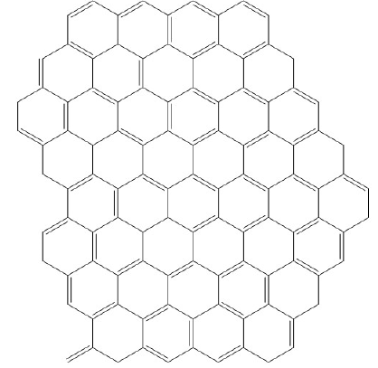
Figure 1 – Graphene chemical structure.
Graphene is a new material that has been receiving a large amount of research attention since it was first isolated in 2004. It has remarkably high theoretical properties that make it ideal for a wide range of applications. It is an allotrope of carbon defined by a 2-D planar orientation just one atom thick and oriented in a densely packed benzene-ring structure as shown in Figure 1. Carbon has four electrons in its valence shell. The electron orbitals form planar bonds with three neighboring carbon atoms at 120 degree intervals.
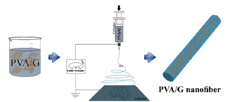
Figure 8 – Electrospinning Process.
A common method to fabricate nanoparticle fibers is the use of electrospinning, as shown in Figure 8. A precursor gel of nanoparticles is loaded into a syringe equipped with a capillary metal needle. A high-voltage charge is then applied between the metal orifice and grounded collector to generate a thin charged jet. Ultra-fine gel fibers are produced in the form of nonwoven mats by accelerating toward the collector.
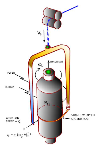
Figure 11 – Bobbin and flyer mechanism.
This mechanism (Fig. 11) is used to collect the fiber after it is spun and imparts longitudinal twist. The bobbin and flyer both rotate in the same direction, with the flyer rotating slightly faster. The overall rotation imparts the longitudinal twist while the relative motion between the two causes the fiber to wrap around the bobbin. The magnitudes of the two rotations can be changed to adjust both the twist rate and the wrap rate.
OBJECTIVES
Drawing and twisting graphene fibers improves their mechanical performance, however current manual methods produce fibers limited to short lengths. Based upon what we learned from talking with Dr. Zhang and his research group as well as observing their current production method, we have established that Dr. Zhang needs a continuous, consistent process for drawing and twisting graphene fibers that has an adjustable output. We established a set of requirements and through the Quality Function Deployment (QFD) process developed a list of specifications.
DESIGN DEVELOPMENT
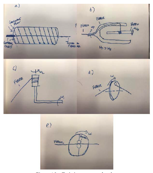
Figure 15 – Twisting concept sketches.
After we evaluated our twisting concepts for basic feasibility, our concepts were (1) twisting via a microfluidic channel, (2) a bobbin-and-flyer mechanism as discussed in our background section, (3) a rotating bobbin attached to an L-shaped arm that is also rotating, (4) a rotating disk that has an off-center hole that the fiber is threaded through, and (5) a pair of rollers that are rotating about the fiber. These concepts are shown in figure 15a-e, respectively.
SELECTED CONCEPT
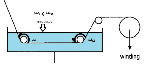
Figure 18 – Drawing bath diagram.
From the results of our two weighted decision matrices, we will be using the two different speed rollers for drawing and the differential concept for twisting. The roller concept is two rollers submerged in a bath of methanol. The later roller is driven slightly faster than the first roller, and friction forces cause the fiber to stretch. This process is shown in figure 18.
MANAGEMENT PLAN
With the completion of this report by the 18th of November, we are perfectly on track as per our Gantt chart in Appendix F. The most prominent outstanding deliverables remaining are the Critical Design Review (CDR), Project Update Report, Hardware Safety Demo, and Final Design Report. The CDR will be built largely upon this report and filled in with detailed design analysis. This will include part drawings for all system components which we will be manufacturing ourselves and specifications supporting selections for any off-the-shelf components.
Our CDR deadline is February 7th, 2017. Our Project Update Report will cover progress on our project manufacturing through the end of March. It is primarily intended to update Dr. Zhang on the status of the project and will be ready for him by March 16th, 2017. The final Design Report will be built upon CDR and cover the entirety of the project. It will include all of our results from manufacturing and testing to report on the design process as a whole. This report will be done by the Senior Design Expo on June 2nd.
FINAL DESIGN DESCRIPTION
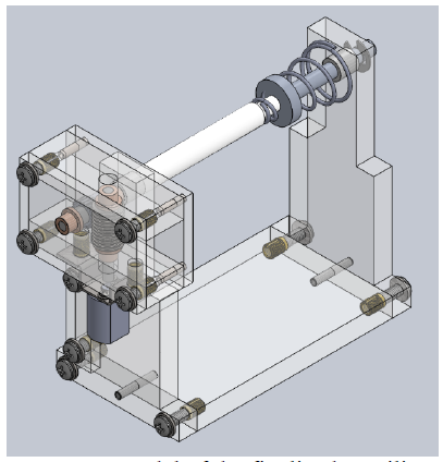
Figure 21 – CAD model of the finalized Auxiliary Roller.
Due to a slight change in the scope of our project, the Auxiliary Roller was designed. Since the twisting speed could not keep up with fiber extrusion speed it became necessary to create a break in the process. The fiber spools around the Auxiliary Roller either after coagulation or after the drawing process. The CAD for the Auxiliary Roller can be seen in figure 21.
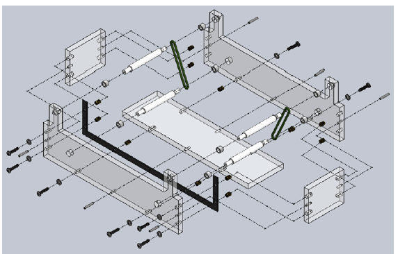
Figure 24 – Exploded bath subassembly.
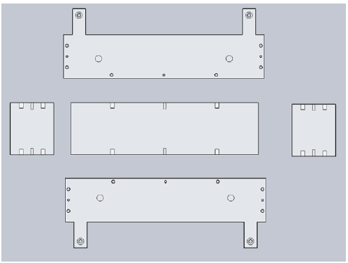
Figure 25 – Bath frame components.
Figure 24 shows an exploded view of the bath, which is made up of the body, rollers, belts, bearings, fasteners, and a silicone gasket. The bath body is comprised of five major pieces: the base, two side walls, and two end caps. These are all made out of PVC sheet and shown in figure 25.
The walls must contain mounting surfaces for the rollers, however drilling through holes below the fluid level would increase the propensity to leak. Therefore, it was decided that the bearings the rollers mount to would be placed in blind holes in the surface and the wall thickness must be sufficient to accommodate the blind hole and retain adequate material thickness.
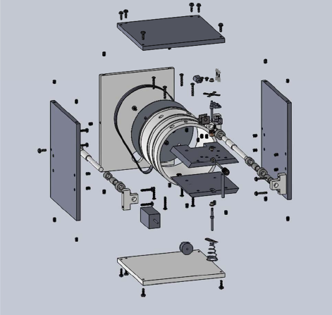
Figure 42 – Exploded view of the entire electronic differential housing assembly.
The Electronic Differential makes use of two motors, one internal and one external, to power both the twisting and spooling movement. The external motor works in the same way a rotary clothes dryer does: the cylinder is powered by a motor and belt combination. In addition to this, the cylinder rests on rollers, or in our case nylon bushings to support the component with minimal frictional losses. To prevent the cylinder from moving throughout the housing, half-inch bands will be cut into the cylinder using a lathe.
MANUFACTURING PLAN
Our manufacturing plan is centered around resources at Cal Poly. We have a total of 39 unique manufactured components between the bath, auxiliary roller, and electronic differential. These components can all be manufactured using a variety of processes available to students for free.
First and foremost, we plan to use the Industrial Technology Department’s waterjet cutter to manufacture the bath walls, gearbox walls, cylinder internal walls, cylinder housing, motor mounts, cylinder backing plate, and spring lever. This means that about half of the components we need to make will be waterjet. According to the shop technicians in the IT Department, the PVC and aluminum sheets we plan to make our parts out of are very typical and almost trivial for a waterjet cutter. Not only will they be easy to convert to the necessary .
DESIGN VERIFICATION PLAN
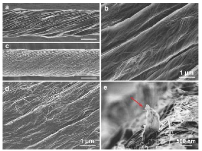
Figure 63 – SEM Images of GO/CNT composite nanofibers.
Ten different GF samples will be observed under the SEM to evaluate both angle and diameter characteristics. In order to ensure availability of the SEM during our testing phase, we plan on scheduling an appointment in advance with the MATE Dept., in order to set apart a time slot of about 3 hours for us to adequately use the SEM to conduct all of our measurements. We also plan on having a MATE grad. student or professor present during the testing in order to ensure that we follow the correct procedures when operating the SEM and obtain as accurate of measurements as possible.
DESIGN REALIZATION
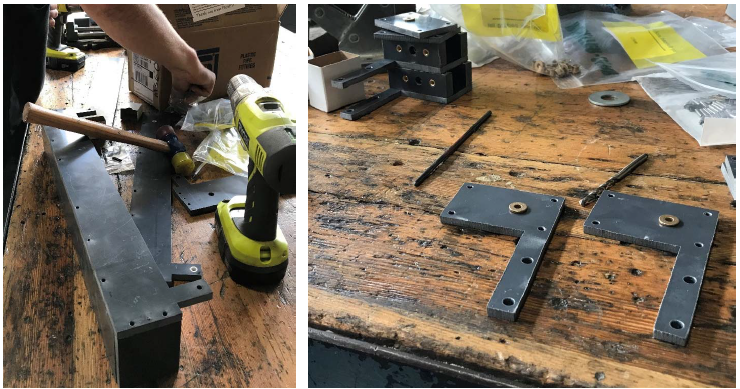
Figure 66 – (left) One of the baths being assembled on a workbench. (right) Gear box components being prepared for assembly.
Care should be taken when assembling these fasteners to not overtighten them. Also, the process of inserting the screws into the brass inserts generated a large degree of heat. Screw heads were often hot to the touch after tightening. This task was best accomplished with an impact driver, so as to not strip the screw heads. Additionally, a rubber mallet was useful for driving alignment pins and then separating the bath halves if necessary. This process is shown in figure 66.
DESIGN VERIFICATION
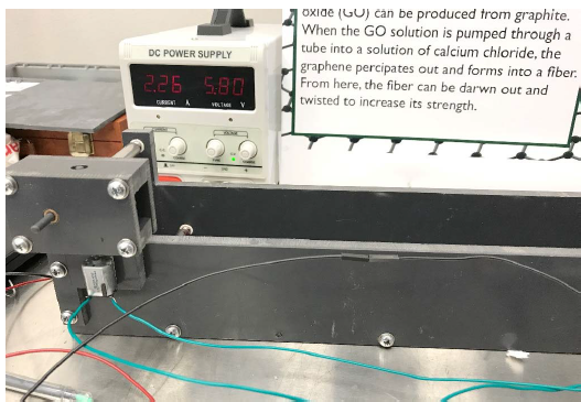
Figure 69 – Large power draw observed during our system level testing.
With the system connected together, we ran a functionality test of the two baths plus the auxiliary roller in series, powered through the control boards, as shown in Figure 68. Due to misalignment, the roller speeds oscillated significantly, creating a “pulsing” effect of the rollers slowing down then speeding up. Also, the system drew roughly 2.26 amps at 5.8 volts, as can be seen in Figure 69. This power also oscillated over time.
CONCLUSIONS AND FUTURE WORK
Currently, the prototype is not ready to be put into use. Due to manufacturing delays, our testing schedule became compressed and there was not enough time to fix larger component issues. As such, the finished prototype has several areas that could use further improvement in future iterations. Misalignment due to manufacturing tolerances and theoretical divergence in our electronics led to loss of expected function. For all of these issues, there are specific remedies that can resolve the issues in later iterations.
The primary cause of function loss is due to friction in the powertrain mechanisms. As mentioned before, this stemmed from the waterjet process. To improve this, waterjet cutting should be used for outer profiles, however all holes should be located using more precise methods, such as a mill. Additionally, the gear box axle holes should be drilled after the boxes are assembled, to further reduce the risk of misalignment due to tolerance stack-up. Removing this misalignment would significantly reduce load on the motor and allow improved functionality.
Beyond just fixing misalignment issues, the bronze bushings created a higher amount of friction than anticipated. These should be replaced with conventional ball bearings – or thrust bearings as appropriate – to further reduce friction. This would allow more torque to be delivered to the shafts, and thus give more control over the motor speed. Using ball bearings may not be possible due to the chemical environment in the bath, however reducing the friction in the gear boxes would be a significant fix.
Source: California Polytechnic State University
Authors: Isaias Diaz | Greg Lane | Robert Sekerak