ABSTRACT
This project will analyze the Z-wing configuration. The Z-wing configuration is basically an airplane that has one of the wings placed at the forward section of the fuselage and the other wing placed on the other side far aft at the fuselage.
This configuration creates a lot of different and unwanted forces and moments due to a differential in lift and drag between both the wings and the main objective with this thesis is to get a Z-wing to fly straight and level flight without these strange and unwanted forces and moments over it.
Therefore the contribution of the wings different parameters to different moments and forces have been mapped out. Parameters such as the angle of incidence, wing span, dihedral, placement of wings etc.
All the calculations done regarding the aerodynamic forces on the Z-wing have been performed in the Tornado, which is a program that runs in MATLAB and uses Vortex Lattice Method for its calculations.
The outcome was that a steady level flight was possible. The configuration does have a lot of disadvantages. It will be very difficult to control in pitch, yaw and roll, although a backwards sweep of the front wing and a backwards sweep of the aft wing made roll control much better.
METHODS
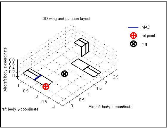
Figure 2.1
Much of the researches in this thesis have been performed in Tornado, which is a program that is implemented in MATLAB and uses the Vortex Lattice Method for calculations. The program didn’t really have the all features that was wanted, but have nevertheless been a good tool for the thesis. In this thesis many variables like angle of incidence, wing area etc. have been changed and analyzed, there isn’t really a feature for this built in to Torn a do and the variables have therefore been varied manually which sometimes have been a very time-consuming.
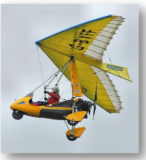
Figure 2.21 Pegasus Quantum 145 – 912
The most common way to control an airplane is to have a pair of ailerons, a rudder and an elevator. Bigger airplanes often have a couple of spoilers on the wings as well. As a last resort it’s also possible to control an airplane with its engine(s). Some airplanes control their way through the air by moving the center of gravity in relation to the wing, usually a Rogallo wing. This kind of wing is shown in the picture below on a Pegasus Quantum1. On the flying flea (which is a tandem wing aircraft) the angle of incidence was variable to be able to use the whole wing as an elevator (the picture to the right is showing a HM1000 Balerit2, which is based on the same concept as the flying flea).
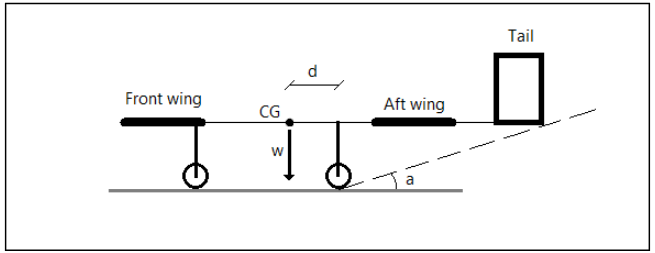
Figure 2.30
For the ground roll, its seen on the figure that the distance between the center of gravity and the main landing gear is important. The moment from the wings that will pitch the nose up at ground roll have to overcome the moment from the weight and the distance between the center of gravity and the main landing gear. When that solution is solved the most aft position for the main landing gear is decided. The most forward position of the landing gear is decided by the angle “a” also seen in the figure below. If this angle is too small the airplane will be vulnerable to tail strikes.
RESULTS / DISCUSSION
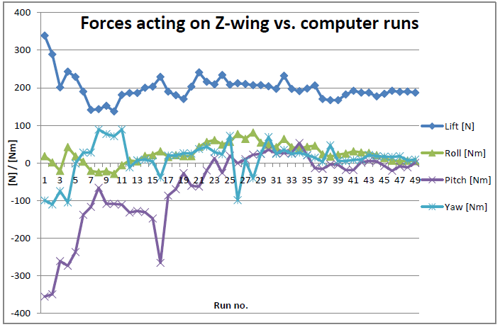
Figure 3.26
The original model for this part of the thesis was, as with many other analyses in this thesis, the basic Z-wing described in title 2.1 was used. This basic Z-wing also stood as a model from which the steady flying Z-wing shouldn’t differ too much. As stated before in methods; this part was very much about trial and error. But the workload was reduced after having the couplings between the different parameters and their contribution to different moments mapped out.
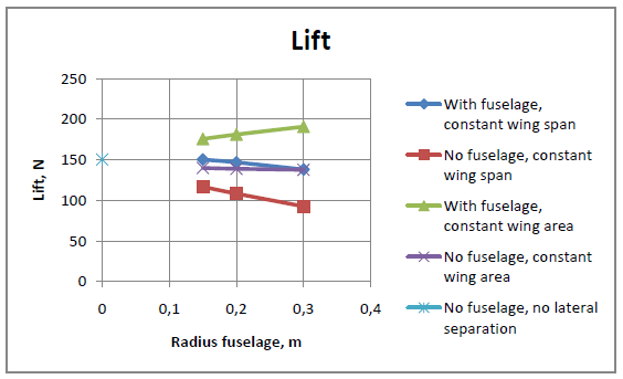
Figure 3.43
As stated before, an analysis of how the body affected the induced drag and thereby the lift was done. The graphs on the next page show the results. These results are also shown in tables in Annex G. The difference in these different graphs is found in the axes; in one graph the axis describes the radius of the fuselage contra the lift while the second graph is treating the ratio between the radius of the fuselage and the span of one wing contra the lift.
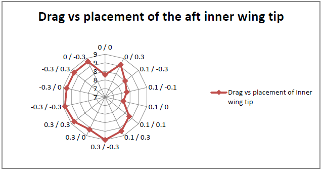
Figure 3.47
The graphs show that most lift is created when the tips are having a little gap between each other. This is probably due to a combination of the down sweep from the front wing and the vortex of the front wing cancelling out some of the vortex being created at the aft wing. On the next page a graph showing the drag for the same conditions are presented and there it’s seen that the lowest value of drag occurs when the wings are having a small gap and the wings are kept level to each other.
CONCLUSIONS
Conclusions from the Analysis of the Z-Wing
From the very beginning of the work with this thesis, the Z-wing seemed like a very complex type of wing configuration and this thesis have definitely showed this.
The thesis has also showed that a straight and level flight is achievable with a Z-wing configuration, even though it brings many problems. For this configuration and size of airplane (UAV) the lift force were reduced to about 55% of its original value in an untrimmed state. That is a huge loss in lift. Besides that, controlling the Z-wing will be a small project for itself. With the front wing swept backwards and the front wing being swept forwards most of the unwanted pitch moment due to roll control is lost. But the tail solution, either with a tilted fin or the solution in this thesis, an asymmetric T-tail, will complicate at least control in pitch.
For the question if a vertical/horizontal fin/stabilizer is necessary for a trimmed flight, this thesis really don’t bring an answer. The different tries that have been done here shows that it is very hard to find a trimmed state without a fin or a stabilizer, but they haven’t showed that it would be impossible.
If it’s assumed that all problems with the controlling of the Z-wing are getting solved, which they probably can be, the fuselage of the airplane still would have to withstand a huge amount of torque. For example a simplified calculation showed that the fuselage would have about 370 Nm of torque along the longitudinal axis, for a Z-wing weighing 50 kg.
But the Z-wing has to be lighter than that, the configuration that achieved straight and level flight had a lift of about 190 N, with a total wingspan of 2.8125 meters and a length of 5 meters. So, it’s crucial that the Z-wing configured UAV is made of lightweight and very strong material. The fuselage would preferably be made of some kind of carbon fiber tubing.
With all that said, not much speaks for the Z-wing configurations advantage. But the Z-wing will always look odd, it will always look strange and if people look at a flying Z-wing they will probably say “It’s amazing that thing can fly”. For that purpose, it will always be worth the effort to get one flying.
Source: Malardalen University
Author: Joakim Aven
>> Matlab Project Pdf Free Downloads for Aeronautical Engineering Students
>> MATLAB based projects for Mechanical Final Year Students
>> Mechanical Projects based on Mechanics for Final Year Students