ABSTRACT
Supplemental damping can be used as a cost-effective method to reduce structural vibrations. In particular, passive systems are now widely accepted and have numerous applications in the field. However, they are typically tuned to specific excitations and their performances are bandwidth-limited. A solution is to use semiactive devices, which have shown to be capable of substantially enhanced mitigation performance. The authors have recently proposed a new type of semi-active device, which consists of a variable friction mechanism based on a vehicle duo-servo drum brake, a mechanically robust and reliable technology.
The theoretical performance of the proposed device has been previously demonstrated via numerical simulations. In this paper, we further the understanding of the device, termed Modified Friction Device (MFD) by fabricating a small scale prototype and characterizing its dynamic behavior. While the dynamics of friction is well understood for automotive braking technology, we investigate for the first time the dynamic behavior of this friction mechanism at low displacements and velocities, in both forward and backward directions, under various hydraulic pressures. A modified 3-stage dynamic model is introduced.
A LuGre friction model is used to characterize the friction zone (Stage 1), and two pure stiffness regions to characterize the dynamics of the MFD once the rotation is reversed and the braking shoes are sticking to the drum (Stage 2) and the rapid build up of forces once the shoes are held by the anchor pin (Stage 3). The proposed model is identified experimentally by subjecting the prototype to harmonic excitations. It is found that the proposed model can be used to characterize the dynamics of the MFD, and that the largest fitting error arises at low velocity under low pressure input. The model is then verified by subjecting the MFD to two different earthquake excitations under different pressure inputs. The model is capable of tracking the device ׳s response, despite a lower fitting performance under low pressure and small force output, as it was found in the harmonic tests due to the possible nonlinearity in Stage 2 of the model.
BACKGROUND
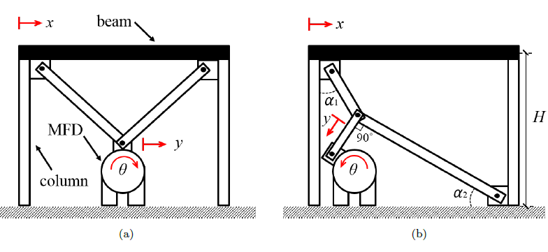
Figure 1: MFD placement within bracing systems: (a) chevron con guration; and (b) toggle con guration. Red arrows illustrate displacement.
Fig. 1 illustrates two possible configurations of the MFD installed within a bracing scheme. The first one is a chevron bracing configuration, and the second one is a toggle bracing configuration. The toggle bracing configuration has the advantage of largely amplifying the movement of the floor drift transmitted to the damping device, which would allow the MFD to attain the Coulomb friction faster, but is more expensive to install.
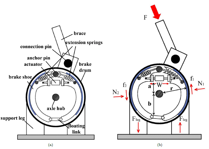
Figure 2: Schematic representation of the MFD: (a) internal components; and (b) diagram of forces.
The duo-servo drum brake illustrated in Fig. 2 is slightly di erent that the one presented. The fabricated prototype presented in this paper is an altered version of a vehicle brake, as it will be described later. A duo-servo vehicle brake exhibits a gap between the anchor pin and the shoes, which is a necessary feature to provide continuous self-energizing throughout both shoes.
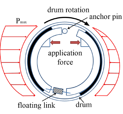
Figure 3: self-energizing effect distribution for duo-servo drum brake.
The self-energizing mechanism amplifies the actuation force W by a factor C for a total friction force F = CW. It is a result of a static moment generated from the position and geometry of the shoes with respect to the drum. As the drum rotate and the braking mechanism is applied, the drum gradually drags the shoes along the circumference which produces an increasing friction force, as shown in Fig. 3.
DYNAMIC MODEL
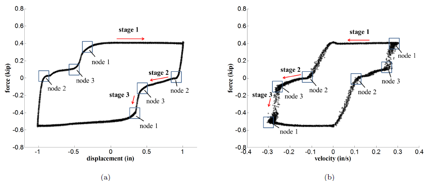
Figure 5: Dynamic response of the MFD under hydraulic pressure of 1200 psi: (a) force-displacement plot (0.05 Hz); and (b) force-velocity plot (0.05 Hz).
The operational performance of the MFD over a full forward and backward motion is characterized by friction dynamics over most of the rotation. The presence of a gap between the anchor pin and braking shoes, as discussed above and shown in Fig. 2, is responsible for a discontinuity in the friction dynamics when the rotation is reversed.
Upon rotation, the leading shoe sticks to the drum until it hits the anchor pin. During this process, the MFD behaves like a stifiness element. Once the leading shoe hits the anchor pin, there is a rapid build up in the resisting force, until the friction dynamics is recovered. A typical response of the MFD over an harmonic excitation period is shown in Fig. 5 to illustrate these dynamic stages (taken at 1 in, 0.05 Hz, and 1200 psi constant pressure input).
IDENTIFICATION OF MODEL PARAMETERS
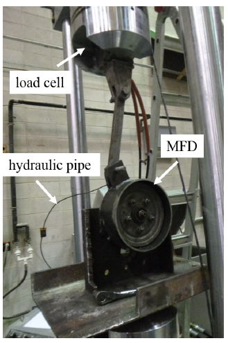
Figure 6: Experimental setup.
Tests were displacement-controlled, induced by an MTS 810 material testing system. Force and displacement data were recorded by the MTS data acquisition system at a 100 Hz sampling rate. The experimentally measured motion signals were used as input for the dynamic model.
The experimental setup is shown in as shown in Fig. 6. Each test was ran over 10 cycles. The characterization of the parameters is based the average value of all cycles. The model characterized in this section will later be validated under a wider range of displacements and velocities by subjecting the device to earthquake excitations.
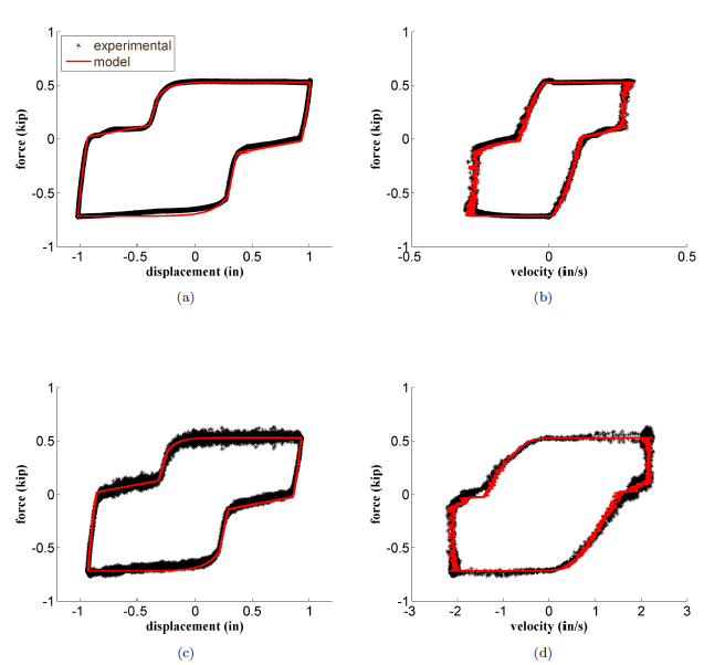
Figure 11: Harmonic test at 1500 psi: (a) force-displacement (0.05Hz); (b) force-velocity (0.05Hz); (c) force-displacement (0.5Hz); (d) force-velocity (0.5Hz).
Fitting results from the model are presented in fig. 11. Experimental results obtained under 0.5 Hz show more noise with respect to results obtained at 0.05 Hz, likely due to chattering. This phenomenon will require further investigation. Results show a good fit between the experimental results and the model.
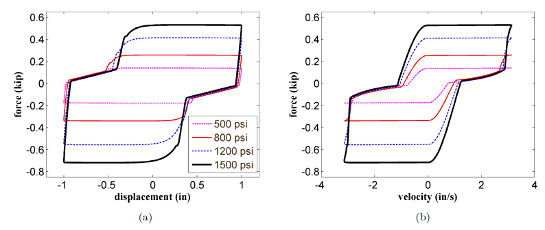
Figure 12: (a) Force-displacement and (b) force-velocity loops for a harmonic excitation of 1 in at 0.50 Hz.
There is a notable fitting discrepancy at low frequency under low pressure (500 psi and 800 psi), which indicate possible nonlinearities during Stage 2. Fig. 12 shows the combined force-displacement (Fig. 12(a)) and force-velocity (Fig. 12(b)) loops plotted using the model for a harmonic excitation of 1 in at 0.50 Hz.
MODEL VALIDATION: EARTHQUAKE EXCITATIONS
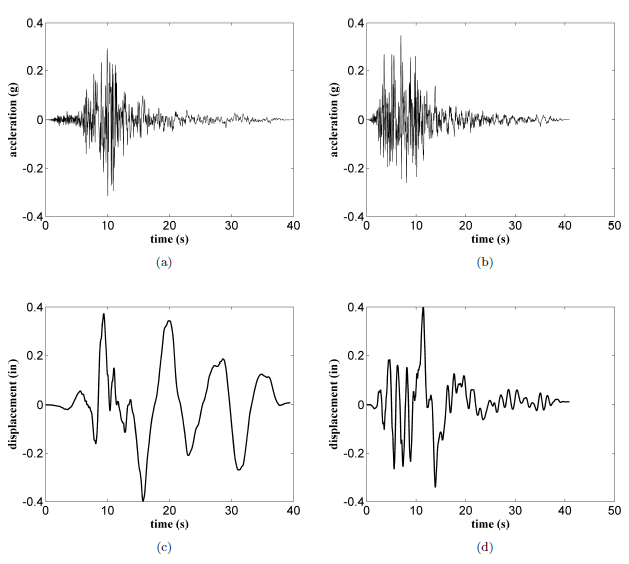
Figure 13: Earthquake input excitations: (a) unscaled ground acceleration (Imperial Valley earthquake) ; (b) unscaled ground acceleration (Kobe earthquake); (c) scaled ground displacement (Imperial Valley earthquake); (d) scaled ground displacement (Kobe earthquake).
Ground displacements were computed by double integrating the ground acceleration, and scaled to a maximum displacement of 0.4 in to match the testing equipment’s limitations at high frequencies. Acceleration and scaled displacement time histories are as shown in Fig. 13. Two different constant pressure values are used in the experiment: 500 psi, a value parameterized above, 195 and 1000 psi, a value not parameterized previously.
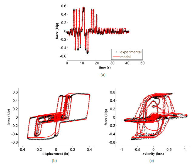
Figure 15: Kobe earthquake at 1000 psi: (a) time history of damper force ; (b) force-displacement loop ; and (c) force-velocity loop.
In particular, Fig. 15(a) shows an overshoot of the estimated force after approximately 20 sec. This overshoot is due to the linear approximation of the damping force when the shoes are slipping (stage 2), further evidenced in Fig. 15(b) by the overestimation of the experimental data for low forces (between approximately -0.15 and 0.15 kip).
SUMMARY AND CONCLUSIONS
We have characterized the dynamic behavior of a novel semi-active friction device designed for structural control. A particular feature of the due-servo drum brake is the discontinuity of the friction dynamics due to the gap between the anchor pin and braking shoes. A 3-stage dynamic model was proposed to characterize this dynamics.
A LuGre friction model was used to model the friction zone (Stage 1), and two pure stifiness regions to characterize the dynamics of the MFD once the rotation is reversed and the braking shoes are sticking to the drum (Stage 2) and the rapid build up of forces once the shoes are held by the anchor pin (Stage 3). A small-scale prototype was fabricated and the parameters of the dynamic model identified by subjecting the device to different harmonic excitations under various pressure inputs. The model was later validated using two different earthquake excitations under two pressure inputs.
Results show that the model was capable of tracking the device’s response, despite a lower fitting performance under low pressure and small force output, as it was found for the harmonic tests during the model identification phase. A possible non-linearity in Stage 2 of the dynamic model is responsible for most of this lower performance. Future investigation will include enhanced modeling of Stage 2’s dynamics by using a nonlinear stifiness element to improve on model fitting, and a second-generation design to reduce the dynamics provoked by the gap between the anchor pin and the braking shoes (Stages 2 and 3) to improve energy dissipation.
The validated model in this research advances the understanding of the dynamic behavior of an automotive braking system used for structural control applications. Integrated in the MFD design, such technology provides a mechanically robust alternative to semi-active control of civil structures. The proposed model can be used to enhance design of structures equipped with MFD, and to develop effective control algorithms.
Source: Iowa State University
Authors: Liang Cao | Austin R.J. Downey | Simon Laflamme | Douglas Taylor | James Ricles