ABSTRACT
Cracking is an important potential failure mechanism for pavement structures. By combining a strain energy-based fracture criterion with conventional fracture mechanics based on the Energy Ratio (ER) concept, crack growth in asphalt can be investigated, and a low temperature Thermal Cracking model (TCMODEL) can be introduced. This study presents the implementation of the Florida cracking model into a Mechanistic-Empirical (ME) flexible pavement design framework.
An improved analysis procedure for better converting raw data from the Superpave Indirect Tensile Test (IDT) into fundamental viscoelastic properties of the asphalt mixture allows for calibration of the TCMODEL. This study involves a detailed review of Florida cracking model and TCMODEL. Finally, a MATLAB tool is prepared for the thermal cracking model to investigate the cause and effect of the problems.
BACKGROUND OVERVIEW
Hot Mix Asphalt (HMA) pavements are typically a layered system. One or more asphalt layers are placed on top of a granular aggregate base layer, which in turn is placed on compacted soil layers. Thermal cracking can form across the width of the pavement if an asphalt pavement is subjected to a thermal loading due to temperature change (Roque et al., 1995). It is one of the most destructive distresses that can occur in asphalt pavements in cold climates. Over the time, various empirical and “mechanistic-empirical” models (Fromm and Phang, 1972; Roque et al., 1995) have been proposed for predicting this distress.
HMA FRACTURE MECHANICS
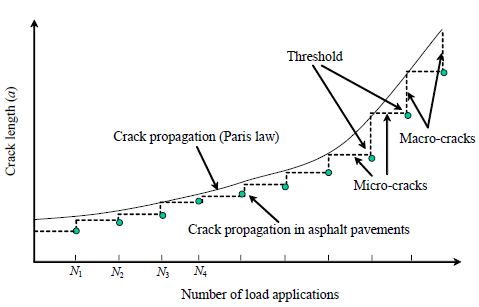
Figure 2. Illustration of Crack Propagation in Asphalt Mixtures (Birgisson et al., 2007)
Zhang et al. (2001a) suggested the existence of a fracture threshold by observing that discontinuous (stepwise) crack growth in HMA materials (Figure 2).
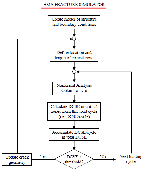
Figure 5. Flowchart of the HMA Fracture Simulator (Birgisson et al., 2007)
An HMA fracture simulator is developed (Birgisson et al., 2007) based on the numerical solution obtained from the viscoelastic displacement discontinuity method by using the dissipated creep strain energy (DCSE) (or permanent damage) threshold concept. Figure 5 shows a flowchart of the HMA fracture simulator.
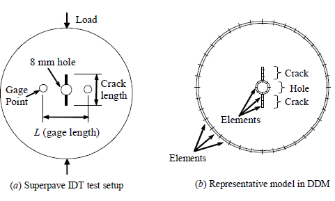
Figure 8. Superpave IDT Test with a Vertical Crack and Its Representative DD Model (Birgisson et al., 2007)
An asphalt disk specimen with a small central hole is subjected to cyclic haversine loads, with 0.1 second loading and 0.9 second rest period in each loading cycle. Two Superpave mixtures were previously produced (a coarse-graded and a fine-graded mix) and tested by Honeycutt (2000) and Zhang (2000). The experiment setup is shown in Figure 8a. The diameter and thickness of the specimen are 150 mm and 25 mm respectively, whereas the hole diameter is 8 mm.
APPLICATION TO TOP-DOWN CRACKING
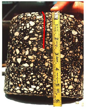
Figure 9. Typical Top-Down Cracking Observed from a Field Core (Birgisson et al., 2004)
Load-related top-down fatigue cracking (cracking that initiates at the surface and propagates downward) commonly occurs in asphalt pavements. This phenomenon has been reported to occur in many parts of the United States, as well as in Europe and China. The typical top-down cracking observed from a field core is shown in Figure 9.
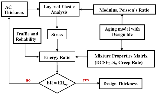
Figure 14. Level 3 M-E Design Flowchart for Top-Down Cracking (Birgisson et al., 2004)
For Level 3 top-down cracking design the ER criterion is used which accounts for the structure and mixture for “averaged” environmental conditions. The design scenario is to determine the asphalt layer thickness for ER ≈ ER optimum at the pavement design life (Birgisson et al., 2004). The Level 3 M-E design flowchart for top-down cracking is shown in Figure 14.
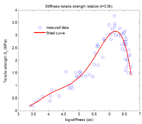
Figure 15. Relation between Mix Stiffness and Tensile Strength (Birgisson et al., 2004)
The tensile strength is an important factor that needs to estimate in the evaluation for the cracking performance of asphalt mixture. Deme and Young (1987) discovered that the tensile strength of mix is well correlated with the mixture stiffness at a loading time t = 30 minutes. In their evaluation work on the low temperature cracking performance, they used the temperature range of –40 to 25oC. These data is digitized and plotted in Figure 15.
REVIEW OF THERMAL CRACK MODEL
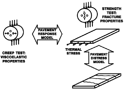
Figure 19. Materials Characterization with the IDT (Witczak et al., 2000)
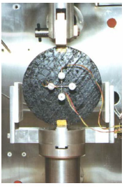
Figure 20. Superpave Indirect Tensile Strength Device (Witczak et al., 2000)
It is viscoelastic properties that control thermal stress development and the fracture properties, and this control the rate of crack development. These properties that can be measured and controlled by the Superpave Indirect Tensile Test (IDT), is shown in Figure 19. A description of the material models on IDT test data and a description of the IDT transformation model are necessary to introduce it in TCMODEL.
IMPLEMENTATION OF THERMAL CRACK MODEL
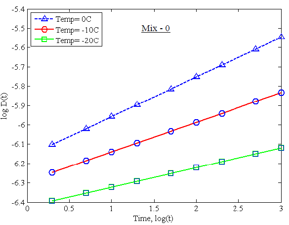
Figure 23. Different Creep Compliance Data at Various Temperatures for Mix-0
The change of creep compliance with the time at different three temperature (-20, -10 and 00C) is calculated. Then these three curves are shifted by using the shift factor for a master creep compliance curve (MCCC) with respect to reduced time. For each of the seven different mixtures, the change of creep compliance value at various temperatures, and the corresponding master curves, is found by using the MATLAB tool. Figures 23 to 36 show the creep compliance data and the MCCC for each of the seven design mixes, respectively.
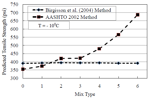
Figure 40. Comparison of Tensile Strength Using Two Methods at -100oC
If the binder content increase in a mix then the tensile strength generally decreases. As per AASHTO formula the tensile strength increases rapidly with the increasing percent of binder content (Figure 40). For the Birgisson et al. (2004) method the tensile strength is higher for mix 1 and 2 because of lower binder content and it decreases gradually for mix 3 to 6 as the binder content increases.
SUMMARY AND CONCLUSION
It is known from the HMA fracture mechanics that non-healable crack initiation or crack growth occurs when the cumulative DCSE reaches the cracking threshold. For modeling the crack growth as an accumulation of micro-damages described by DCSE, the referenced HMA fracture mechanics with a fundamental crack growth threshold is being employed.
In order to implement the DCSE threshold concept in the numerical analysis, a critical (process) zone needs to be defined in front of the crack tip, which is where the maximum limit of the tensile stress occurs, when the DCSE in a zone exceeds the energy threshold, i.e. when it exceeds the DCSE limit, the crack shall propagate by the length of the critical zone, as per the HMA fracture mechanics suggestion, and the direction of the crack growth shall be governed by the maximum dissipated creep strain energy direction.
Future Research Area
The findings of this study represent a start in developing an improved asphalt binder and asphalt mixture specifications, as well as improving the low temperature cracking model. However, this research effort needs to be continued to address the following key issues:
- The critical condition for thermal cracking
- Link the critical condition with the final design stage.
Source: KTH
Author: Prabir Das
>> Civil Engineering Project Topics using Matlab for Final Year Students with Free Downloads
>> 200+ Matlab Projects based on Control System for Final Year Students