ABSTRACT
This study investigates the dynamic response of a railway bridge under train passage. Three load models designed around the Swedish Steel Arrow freight train are tested and compared. A series of Concentrated Forces, a succession of single degree of freedom Sprung-Masses, and a sequence of complex multi-degree of freedom Train Wagons.
The increase in accuracy of the representation corresponds to taking into account the inertial properties of the wagons. The track-bed layer is substitute by a sequence of regularly spaced couple of springs and dampers at the sleeper distance.
Under the assumption of this work, a portion of the ballast vibrates with the sleeper during train passage. Both bridge and rail are modelled under Bernoulli-Euler beam theory. The dynamic behavior of the bridge is investigated in presence or absence of vertical track irregularities. The main conclusions of the report can be summarized as:
- The dynamic amplification attains its maximum value, for every train model, at the critical train speeds of 120 km/h. Proper resonance has also been detected at the speed of 60 km/h in all the simulations;
- The Concentrated Forces model provided an upper boundary of the acceleration response of the bridge while the Sprung-Mass systems a lower boundary. The response of the two models is in very good agreement at non resonance speeds. The simulation with Train Wagons loading does not fit completely this trend, it adds two peaks on the diagram; Besides that, the bridge response lies between the two limits;
- The presence of track irregularities determines a variation of the bridge dynamics only if combined with Train Wagon load model. The Concentrated Force pattern couldn’t detect the modification of the profile while the Sprung-Masses case provided a diagram of maximum acceleration similar to the one over flat rail simply shifted upwards;
- The position of the track irregularities along the bridge influence its dynamics.
DESCRIPTION OF THE CASE STUDY
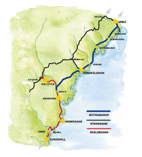
The Bothinia Line (in Swedish Botniabanan) is the new high speed line that serves the east coast of Sweden. This is approximately 190 km long and, as Figure 2.1 illustrates, is delimited between the river Ångermanälven just north of Kramfors and the city of Umeå.

Figure 2.1: The Bothnia Line
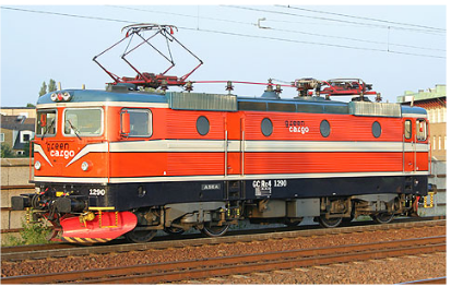
The orange paint with white stripes has been used to recognize the Rc4-s. The last one painted with this scheme is the 1290 model, that can be seen in Figure 2.2. The Swedish court itself wanted the orange to commemorate the Swedish railway’s 150th anniversary.

Figure 2.2: Green Cargo Rc4 1290 i Malmö 2006. Foto Frederik Tellerup
REALIZATION OF THE MODEL
As briefly described in the introductory Chapter, the dynamic problem was modelled and solved using the commercial package ABAQUS. The recurrent geometry of train and rail track, that can be both seen as a succession of units (wagons and sleepers), made the implicit definition of the problem the most convenient way to proceed. The problem was therefore translated in a proper series of instructions in ABAQUS syntax, written in a text file, and sent to the compiler. The length of train and track, then, made the automatized approach via MATLAB the only way to control the process. This Chapter presents the relevant instructions implemented.
The global geometry of the model is characterized by three parts:
- a train model;
- a bridge;
- a railway;
NUMERICAL ANALYSIS
By comparing the eigen frequency of the bridge independent it can be seen that the inter-action bridge-sleepers lowered the natural frequencies of the track and concentrated more modes around the natural frequency of the sleeper fn. This effect can be detected directly by looking at the Figure 4.3d and the two that follows. The relative displacement of the nodes on the rail is greater than the one of the nodes lying on the axle of the bridge. This is the sign that the ballast is vibrating.
MODEL CHECKING
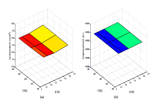
The variation in acceleration and displacement of a point over the bridge deck can reveal if mistakes occurred during the analysis. The first series of graphs presents the variation in acceleration of the bridge mid span due to the movement of four Steel-Arrow wagons. In Figure 5.1 are plotted the results relative to the passage of the Train Wagons model.
DYNSTARR, A MATLAB® TOOLBOX
The routine introduced and described in the previous section treats the dynamic problem in three different parts. The first one takes place in MATLAB environment with the objective of writing, in a text file, the sequence of commands to build the model, move the train, and solve the dynamic problem with ABAQUS. The second one, in ABAQUS environment, solves the equation of the motion derived with FEM approach and saves the result in a proper text file with .dat extension. Finally, back to MATLAB, those result are filtered and presented in plots.
The method does not solve the dynamic equations in MATLAB environment but uses the ABAQUS solver to do that. The strength of this approach is to avoid the manual construction of elaborated finite element models by writing the list of (iterative) implicit instruction with MATLAB. The train velocity is given as a parameter that the user can vary. The method is then customized and automatized. Figure 6.1 presents a diagram of the instructions.
ASSIGNATION OF DAMPING AND CONVERGENCE ANALYSIS
Once the proper Rayleigh damping function has been applied to each of the models a convergence analysis will say which couple of values ( fsampling , lelem ) has to be considered to obtain accurate results. The maximum accelerations and displacements in center span were therefore compared.

Figure 7.6: The Convergence Analysis for the CF
RESULTS
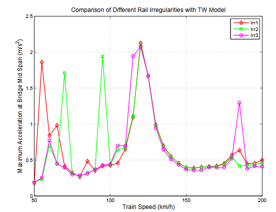
In Figure 8.26 are presented the maximum acceleration at mid span over different corrugated rail. The position of the peaks of the sine function over the rail, even if with small amplitude, changes reasonably the dynamics of the system. Such importance cannot avoid an accurate survey of the condition of the rail before any numerical simulations.

Figure 8.26: Maximum Acceleration at Bridge Midspan
CONCLUSIONS
This study investigated the dynamic response of a railway bridge under train passage. Three load models designed around the Swedish Steel Arrow freight train were tested and compared. A series of Concentrated Forces, a succession of single degree of freedom Sprung-Masses, and a sequence of complex multi-degree of freedom Train Wagons. The increase in accuracy corresponded with the take in consideration of the inertial properties. The slenderness of the infrastructure, suggested to use Bernoulli-Euler beam element for its mesh. Finally, a regularly spaced sequence of springs and dampers interconnected the rail with the bridge and simulated the behavior of the ballast layer. The dynamic response of the bridge is investigated in presence or absence of vertical track irregularities.
Source: KTH
Author: Davide Martino
>> Civil Engineering Project Topics using Matlab for Final Year Students with Free Downloads
>> 200+ Matlab Projects based on Control System for Final Year Students
>> More Matlab DSP Project Ideas for Final Year Students


