ABSTRACT
The use of smart technologies combined with city planning have given rise to smart cities, which empower modern urban systems with the efficient tools to cope with growing needs from increasing population sizes. For example, smart sensors are commonly used to improve city operations and management by tracking traffic, monitoring crowds at events, and performance of utility systems and public transportation.
Recent advances in nanotechnologies have enabled a new family of sensors, termed self-sensing materials, which would provide smart cities with means to also monitor structural health of civil infrastructures. This includes smart concrete, which has the potential to provide any concrete structure with self-sensing capabilities. Such functional property is obtained by correlating the variation of internal strain with the variation of appropriate material properties, such as electrical resistance.
Unlike conventional off-the-shelf structural health monitoring sensors, these innovative transducers combine enhanced durability and distributed measurements, thus providing greater scalability in terms of sensing size and cost. This paper presents recent advances on sensors fabricated using a cementitious matrix with nanoinclusions of Carbon Nanotubes (CNTs).
The fabrication procedures providing homogeneous piezoresistive properties are presented, and the electro mechanical behavior of the sensors is investigated under static and dynamic loads. Results show that the proposed sensors compare well against existing technologies of stress/strain monitoring, like strain gauges and accelerometers. Example of possible field applications for the developed nanocomposite cement-based sensors include traffic monitoring, parking management and condition assessment of masonry and concrete structures.
OVERVIEW
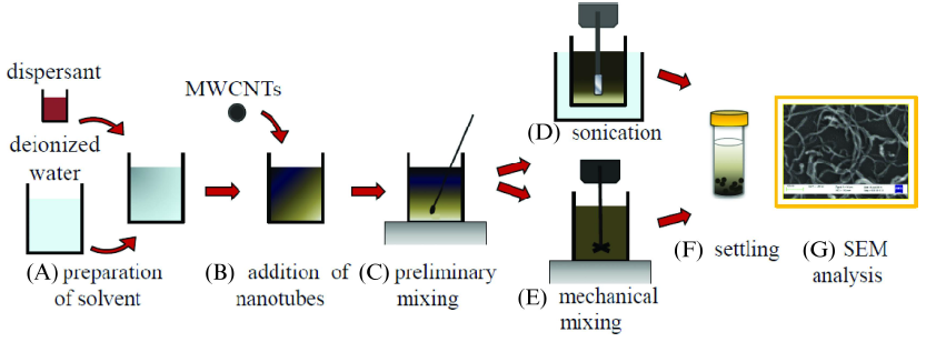
Figure 1. Procedure for investigating the dispersion of MWCNTs in aqueous solution.
First the dispersant was dissolved in 40 g of deionized water (Figure 1(A)). Then, 0.1 g MWCNTs were added and manually mixed (Figure 1(B) and (C)). Assuming a water/cement ratio equal to 0.4 in the composite material, the choice of 0.1 g of MWCNTs in 40 g of water corresponds to a nanotube-cement mass ratio of 0.1%. Dispersants were tested in different amounts: 0.1:1, 1:1 and 10:1 with respect to the mass of the MWCNTs. After preliminary mixing, two alternative procedures were tested and compared: (i) sonication during 30 minutes (Figure 1(D)); or (ii) mechanical mixing for 60 minutes (Figure 1(E)).

Figure 2. Preparation of nanomodified aqueous suspensions. Set up for sonication (A) and mechanical mixing (B); SEM picture of the suspension after mechanical mixing (C).
The ultrasound device was equipped with a probe series VibraCell model 75043, Bioblock Scientific, (Figure 2(A)), with a maximum input power of 750 W. The mechanical mixes were performed with a high speed dissolver, Dispermat LC2, with a speed of rotation of 4000 rev/min (Figure 2(B)). The integrity of the nanotubes was verified via the inspection of scanning electron microscope (SEM) images of the nanomixtures after the mechanical mixing (Figure 2(C)).
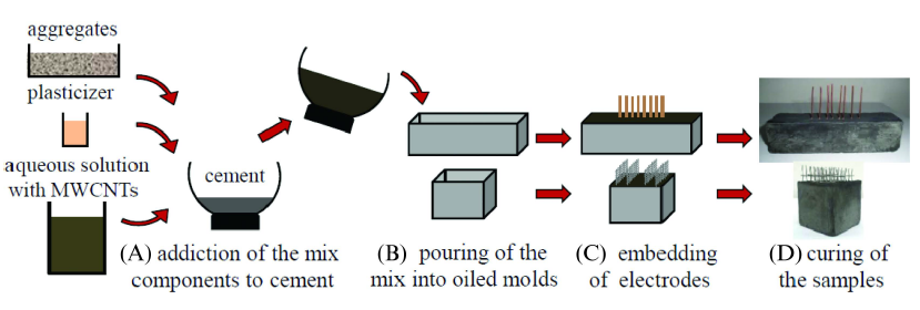
Figure 4. Fabrication process of MWCNT cement-based sensors.
The admixtures were manually mixed (Figure 4(A)). The control of the effective dispersion of carbon nanotubes in the aqueous solution and in the cement paste was performed using a SEM. The resulting mix was poured into oiled molds (Figure 4(B)) and the electrodes were embedded (Figure 4(C)). After proper settling, the samples were unmolded for curing (Figure 4(D)).
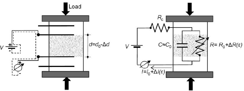
Figure 5. Sketch of the proposed electromechanical behavior of a MWCNT cement-based under compressive load.
Figure 5 shows the electrical circuit proposed by the authors, where C0 is the internal capacitance and Rc represents contact resistance. With an applied compressive axial load, a mechanical deformation occurs, the distance between the electrodes d0 changes, and the change in the electrical properties of the material can be measured.
RESPONSE TO GENERAL LOADING CONDITIONS AND SCALABLE APPLICATIONS
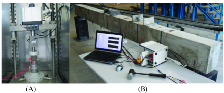
Figure 6. Setup of electromechanical tests: with low speed loads (A) and dynamic loads (B).
The electro mechanical characterization of the nanocomposite sensor has been conducted under static and dynamic loads. Figure 6 shows the experimental setup for both tests. A source measure unit, model NI PXI-4130, provided a stabilized current to the two electrodes through coaxial cables. The electrical current was measured using a high speed digital multimeter, model (NI) PXI-4071, at a sampling rate of 1 kHz for all tested specimens.
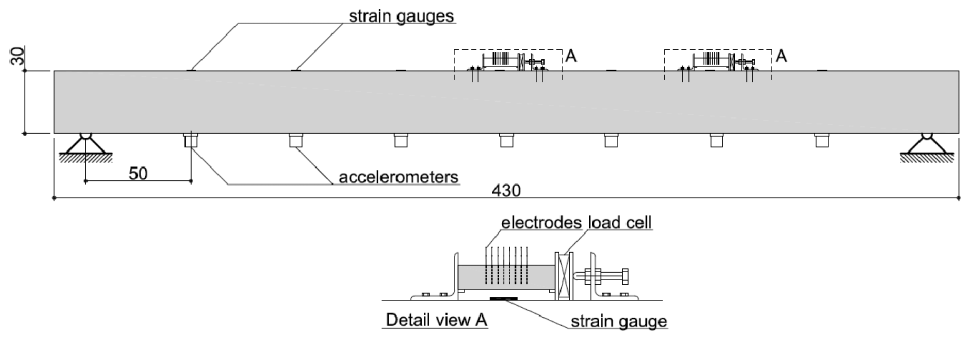
Figure 8. Layout of the experimental setup and plans of the investigated RC beam (dimensions in cm).
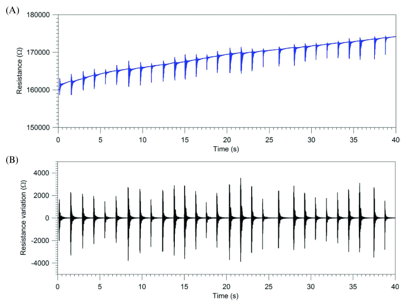
Figure 9. Vibration monitoring of the RC beam using CNTs cement-based sensor placed at mid-span: sensor output before high-pass filtering (A); sensor output after high-pass filtering (B).
Figure 6(B) shows the experimental setup, while Figure 8 represents a sketch of the main elements of the test. The output of the sensor was sampled at 1000 Hz. Before the start of each experiment, a constant tension of 15 V was applied to the sensor for 30 minutes to reduce the effect of polarization. Figure 9 shows the time history of the acquired data: the raw data (Figure 9(A)), and the signal after a high pass filtering above 10 Hz (Figure 9(B)), which eliminated the residual polarization effect.
ELECTROMECHANICAL MODELLING
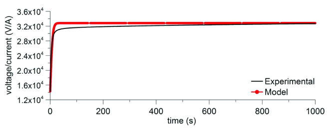
Figure 10. Comparison between experimental results and analytical predictions for the step response of CNTs cement-based sensor with distance between the active electrodes of 1 cm.
Step response tests were conducted in response to a constant voltage difference of 1.5 V for different electrode distances d0. For each value of d0, the current output was measured at a 1 kHz sampling rate for 1 hour. Output data were optimally fitted to identify salient parameters (of R0, R and C). Figure 10 shows the comparison between experimental results and model predictions in case of a distance between electrodes of 1 cm.
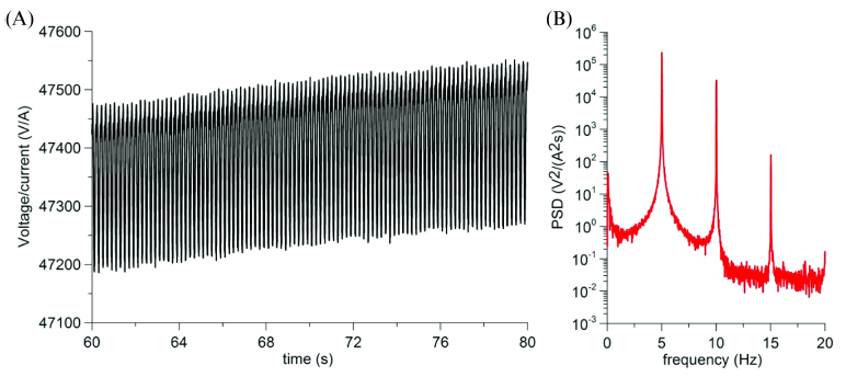
Figure 11. Resistance variation (A) and PSD (B) of the output of CNTs cement-based sensor under 5 Hz sinusoidal axial loading.
After the identification of the model parameters, electromechanical behavior of the CNT cement-based sensors was examined under dynamic tests. Figure 11 represents the time history of the ratio between the output current and the step input voltage (A) and its power spectral density (PSD) (B) under harmonic axial loads of 5 Hz.
PROSPECTIVE APPLICATIONS IN SMART CITIES
CNT-based cementitious sensors represent a novelty in the field of structural engineering and SHM. To the best of the knowledge of the authors, they are yet to be implemented in the field. Possible applications are various and multidisciplinary. These nanocomposites are suitable for fabricating smart self-sensing sensors, which can be used to improve city operations and management by deploying large arrays of distributed sensors, at low cost. With proper algorithms, it is possible to create an automatic link between the sensor’s signal and the state of interest, which would enable direct decision making on a system operation and management perspective.
CONCLUSION
This paper presented an overview of the current research on novel piezoresistive nanocomposite cementbased sensors. After a brief state-of-art, the technology was described and demonstrated, and future challenges were examined. In particular, this new generation of smart cementitious sensors has both resistive and capacitive characteristics, and has self-sensing capability for static and dynamic loads, which includes vibration signatures.
Experimental tests demonstrated performance comparable to conventional monitoring sensors such as accelerometers and strain gauges. Moreover, the sensor exhibits a very high electrical sensitivity compared with off-the-shelf resistive sensors. The results reflected that the multifunctional cementitious materials have promising applications to enable smart cities. Examples of applications include smart slabs for weigh-in-motion sensing, smart materials for rapid condition assessment of civil infrastructure and other applications described within the paper.
Source: Iowa State University
Authors: Antonella D’Alessandro | Filippo Ubertini | Simon Laflamme | Annibale L. Materazzi