ABSTRACT
Implementation of high performance controllable damping devices can ameliorate cost-e ectiveness of structural systems for mitigation of natural hazards. However, the applications of these damping systems are limited due to a lack of 1) mechanical robustness; 2) electrical reliability; and 3) large resisting force capability. To broaden the implementation of modern damping systems, a novel semi-active damping device is proposed.
The device, termed Banded Rotary Friction Device (BRFD), has enhanced applicability compared to other proposed damping systems due to its cost-effectiveness, high damping performance, mechanical robustness, and technological simplicity. Its mechanical principle is based on a band brake, which results in a high amplification of the applied force while enabling a variable control force. The theoretical model of the BRFD is presented and experimentally verified by subjecting a prototype to various harmonic loads.
Results show that the prototype BRFD is capable of a maximum force of 45 kN (10 kips) using only a 267 N (60 lb) actuation force, therefore providing a mechanical advantage of 169. A 3-stage dynamic model previously developed by the authors can successfully be used to model the dynamic behavior of the BRFD. Keywords: Variable friction, semi-active device, structural control, vibration mitigation, supplemental damping, modi ed friction device
BANDED ROTARY FRICTION DEVICE
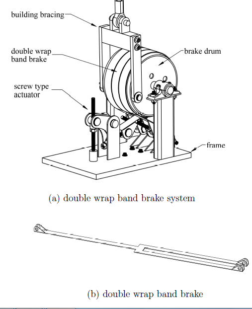
Figure 1: banded rotary friction device.
A 45 kN (10 kips) capacity prototype was fabricated based on the schematic shown in Fig. 1a. The at double wrap band is illustrated in Fig. 1b. The band is lined with friction material and wrapped 670 degrees around the circumference of the steel drum and anchored at both ends. The single end of the band is attached to an actuation mechanism consisting of a threaded rod for the purpose of varying the force applied to the band brake, and the double end of the band is anchored to the rigid frame.
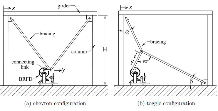
Figure 2: Two possible configurations for the BRFD installed within a building’s lateral load resisting structural system.
Fig. 2 shows the BRFD installed in two possible configurations associated with a building lateral load resisting system. Fig. 2(a) is a chevron system that transduces interstory drift δ into rotation θ of the BRFD via the addition of a connecting link. Fig. 2(b) is a toggle bracing configuration. The toggle bracing is used in structural motion engineering to amplify the interstory drift.
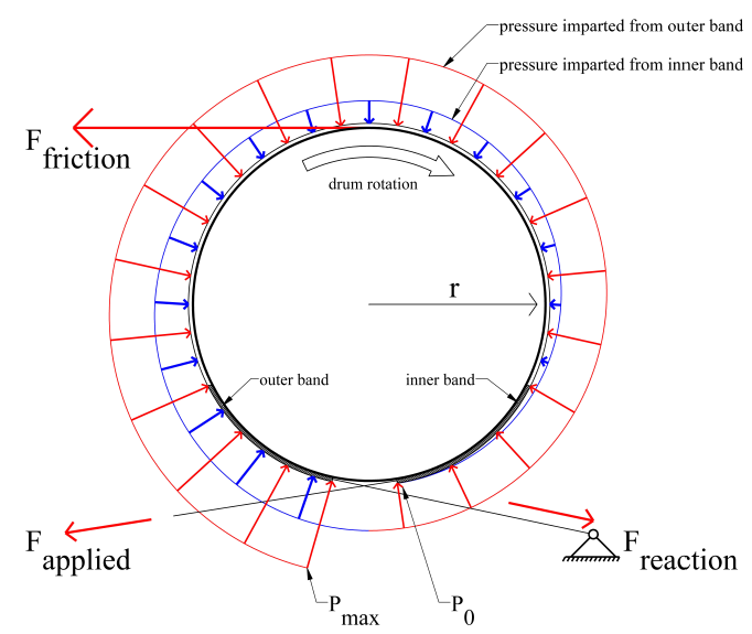
Figure 3: Forces acting on the BRFD.
The friction force of the BRFD is generated by the drum rotating through the stationary band. The band is anchored at one end (called the slack end), where an input force (Fapplied) is applied to the band, resulting in a reactionary force (Freaction) at the opposite end, as shown in Fig. 3. When rotation of the drum is initiated, a friction force (Ffriction) is generated opposing the rotation of the drum at the interface between the friction material and the drum.
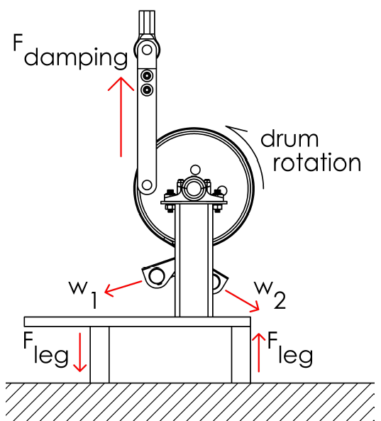
Figure 4: Schematic of the side view of the BRFD.
A schematic of the side view of the BRFD is shown in Fig. 4, where forces w1 and w2 can be either (Fapplied) or (Freaction) depending on the direction of rotation of the drum. This design implementation allows for the damper to take advantage of the positive servo effect in both directions of rotation. The BRFD is designed to sit on two support legs that produce opposite forces Fleg that counteracts the moment produced by the friction forces on the drum.
DYNAMIC MODEL
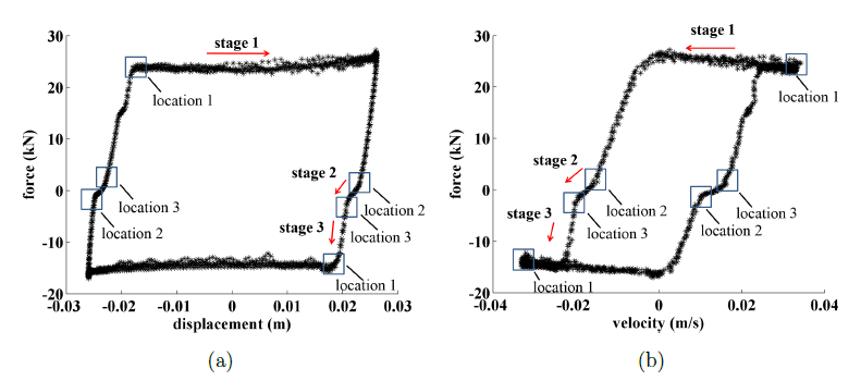
Figure 5: Dynamic response of the BRFD under applied force of 133 N (30 lb) : (a) force-displacement hysteretic response (0.2 Hz); and (b) force-velocity hysteretic response (0.2 Hz).
The authors have previously proposed a 3-stage dynamic model based on a modified LuGre model for characterizing the friction behavior of the first generation of a rotary damping device (i.e., the MFD). This particular dynamic model was useful at characterizing the drop in force that occurs when the rotation of the drum is reversed. As it will be observed in the experimental results presented herein, the BRFD still exhibits a small drop in force upon reversal and the 3-stage dynamic model therefore still applies. This can be observed in Fig. 5 under “stage 2”.
EXPERIMENTAL VALIDATION
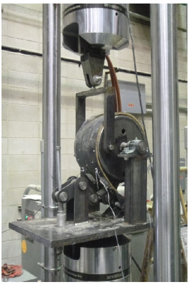
Figure 6: BRFD testing setup.
A load cell was placed between the BRFD’s frame and the activation mechanism for measuring the applied forces. The damping force generated by the BRFD was measured via a load cell located in the head of the testing machine. The test setup is shown in Fig. 6, with the BRFD in its fully un-actuated position. The testing of the BRFD was limited to its designed 45 kN (10 kips) damping force capacity.
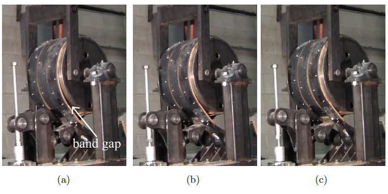
Figure 7: Band gap varying with the applied forces, (a) 35 N; (b) 66 N ; (c) 267 N;
Fig. 7 shows the changing band tension for applied forces of 35, 66, and 267 N. The change in force results in a change in the gap between the friction material on the bands and the drum, this changing distance is exhibited in Fig. 7a through Fig. 7c. These changes are a function of the forces applied to the band. These frames were taken while the drum was in a backwards (clockwise) rotation, where the two exterior bands are acting as the fixed or reactionary ends.
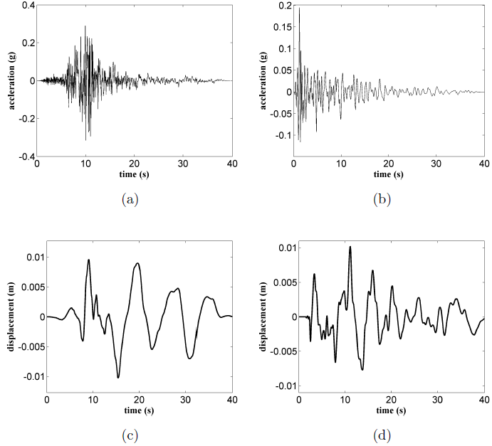
Figure 12: Earthquake excitations.
Figure 12: Earthquake excitations: (a) unscaled ground acceleration (Imperial Valley earthquake) ; (b) unscaled ground acceleration (Hollister earthquake); (c) scaled ground displacement (Imperial Valley earthquake); and (d) scaled ground displacement (Hollister earthquake).
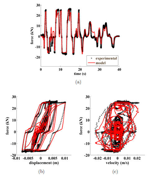
Figure 16: Hollister earthquake at 133 N (30 lb): (a) time history of damping force ; (b) force-displacement loop ; and (c) force-velocity loop.
There is a good match of the theoretical model with the experimental data for both applied forces. A matching discrepancy is clearly observable under the Hollister earthquake at around 25 sec (Fig. 16(a)). This is due to linear ap proximation of the damping force during a change in the rotational direction of the drum where backlash is present. This overshoot is also present in the Imperial Valley response, and can be observed at a small magnitude at around 14 sec.
SUMMARY AND CONCLUSIONS
In this paper, a novel variable friction damper for structural control applications was presented. The device, termed Banded Rotary Friction Device (BRFD), is based on the well-accepted and mature band brake technology. This makes the BRFD a mechanically robust, semi-active damping system. It is capable of providing large damping forces with a substantially lower applied force due to its positive servo effect.
A prototype of the BRFD was fabricated and experimentally validated. The dynamic tests were conducted under harmonic loads at different frequencies and applied forces. Results show that the prototype BRFD is capable of producing a maximum 45 kN (10 kips) damping force. A 3-stage dynamic model was introduced and model parameters were identified based on test results.
Results show that the model could be used to accurately model the dynamic behavior of the device. The experimental mechanical advantage demonstrates that the device was capable of a force amplification in the range of 125-150 times the applied force. These numbers show agreement with theoretical values. The proposed device and its model are further validated using nonstationary excitations consisting of two earthquake time series. Results demonstrated that the BRFD behaves as designed under non stationary excitations.
The validated prototype and friction model presented in this research advances the potential for the implementation of semi-active friction devices. The BRFD is the second generation of rotary damping systems designed by the authors. It was specifically engineered to minimize the backlash effect and increase the maximum damping force by an order of magnitude. Results showed that the BRFD’s has been successful at attaining both objectives, therefore making it a mechanically robust device capable of high variable friction force.
Source: Iowa State University
Authors: Austin R.J. Downey | Liang Cao | Simon Laflamme